3.4 Drawing Requirements
3.4.1 Drawing Production
MDOT MAA requires that all CAD files be provided in AutoCAD DWG format in compliant with Section 3.1.4.1 Approved Software. The standards defined in this standard are specifically for AutoCAD environments. For those consultants and sub-consultants who do not use AutoCAD, it is their responsibility to ensure that files translated to AutoCAD adhere to these standards and that the quality of the data is not degraded in the translation process before delivery.
3.4.1.1 Drawing File Format
Electronic drawings shall be created and maintained in native AutoCAD vector file format (DWG). All drawings shall be void of duplicate entities. The following should be avoided:
Translations between vector file formats (DWG and DGN).
Delivery of Drawing Exchange Format (DXF) files, unless mandated by special requirement in this standard.
Use of the following CAD entities:
1. doughnuts
2. segments
3. solids and traces
4. point entities
5. custom fonts
Patterns or line types or styles
Special characters such as nested blocks, nested or circular Xrefs (reference files)
Infinite lines
Zero length lines
3.4.1.2 Creation of CAD Files
All CAD drawing files should be created at full-scale (1-to-1). Drawing borders are referenced into paper space with insertion point 0, 0 and a scale of 1. Refer to Table 3-1, Scale Factor and Text Height Conversion Chart for standard engineering, architectural and mapping scale factors and text heights to be used in model space for full size drawings.
Plotted Scale |
Scale Factor |
Plotted Text Height |
|||
|
1/8”=1’-0” |
96 |
9.6” |
12” |
18” |
24” |
|
3/16”= 1’-0” |
64 |
6.4” |
8” |
12” |
16” |
|
1/4”=1’-0” |
48 |
4.8” |
6” |
9” |
12” |
|
3/8”= 1’-0” |
32 |
3.2” |
4” |
6” |
8” |
|
1/2”=1’-0” |
24 |
2.4” |
3” |
4.5” |
6” |
|
3/4”=1’-0” |
16 |
1.6” |
2” |
3” |
4” |
|
1”= 1’-0” |
12 |
1.2” |
1.5” |
2.25” |
3” |
|
1 1/2”=1’-0” |
8 |
.8” |
1” |
1.5” |
2” |
|
3”= 1’-0” |
4 |
.4” |
.5” |
.75” |
1” |
|
6”= 1’-0” |
2 |
.2” |
.25” |
.375” |
.5” |
|
12”= 1’-0” |
1 |
.1” |
.125” |
.1875” |
.25” |
|
1”= 10’ |
120 |
1’ |
1.25’ |
1.875’ |
2.5625’ |
|
1”=20’-0” |
240 |
2’ |
2.5’ |
3.75’ |
5’ |
|
1”=25’-0” |
300 |
2.5’ |
3.125’ |
4.6875’ |
6.26’ |
|
1”=30’-0” |
360 |
3’ |
3.75’ |
5.625’ |
7.5’ |
|
1”=50’-0” |
600 |
5’ |
6.25’ |
9.375’ |
12.5’ |
|
1”=100’-0” |
1200 |
10’ |
12.5’ |
18.75’ |
25.0’ |
|
1=10 |
10 |
1 |
1.25 |
1.875 |
2.5 |
|
1=20 |
20 |
2 |
2.5 |
3.75 |
5 |
|
1=30 |
30 |
3 |
3.75 |
5.625 |
7.5 |
Table 3-1, Scale Factor and Text Height Conversion Chart
Drawing Sheet Format
MDOT MAA-approved drawing formats include common drawing features such as boundary geometry, title block data, filename, pathname, and title block geometry.
The most current MDOT MAA-approved drawing formats, templates and seed files are stored in AIRPortal under General > PEGS Reference Documents. Consultants and sub-consultants have access to the most current resources to perform their services compliant with MDOT MAA’s current standards. Consultants are responsible to review the PEGS Reference Documents library to ensure they are using the most current versions.
Drawing Size
The MDOT MAA standard drawing size is ANSI D (22" X 34") full size and ANSI B (11” X 17") half size. Other sizes are allowed only as needed. Drawing sheet size and margins must follow the specifications shown in Table 3-2, Standard Drawing Sizes. These margins are configured in the Standard Borders. Apply ANSI Y14.1 for any information not provided in this standard, but required on drawing sheet size.
|
Size Designation |
Vertical |
Horizontal |
Margin |
||
|
Horizontal |
Vertical |
||||
|
Left |
Right |
||||
|
ANSI B |
11" |
17" |
0.25" |
0.75" |
0.25" |
|
ANSI D |
22" |
34" |
0.50” |
1.50" |
0.50" |
Table 3-2, Standard Drawing Sizes
Sizing Drawing Formats for Scaled Drawings
Each feature shall be drawn in the CAD model file at full size (1 : 1). The data should be scaled to fit the desired paper size at the correct scale through a view port in paper space. This can be done in AutoCAD using the zoom command and entering nXP where n is the scale factor required and XP remains constant. Table 5-3 provides the necessary scale factors needed to calculate each reduced plot size.
Plot Scale |
Drawing Area Size (H x W) * |
Scale Factor nXP |
|
|
|
B (9.5” x 13.25”) |
D (19” x 26.5”) |
|||
|
1/8”=1’-0” |
76’ x 106' |
152’ x 212’ |
0.0104XP |
Architectural Units |
|
3/16”= 1’-0” |
50.7’ x 70.7’ |
101.3’ x 141.3’ |
0.0156XP |
|
|
¼”=1’-0” |
38’ x 53’ |
76’ x 106’ |
0.0208XP |
|
|
3/8”= 1’-0” |
25’ x 35’ |
50.7’ x 70.7’ |
0.0312XP |
|
|
½”=1’-0” |
19’ x 26.5’ |
38’ x 53’ |
0.0416XP |
|
|
¾”=1’-0” |
12.7’ x 17.7’ |
25.3’ x 35.3’ |
0.0625XP |
|
|
1”= 1’-0” |
9.5’ x 13’ |
19’ x 26.5’ |
0.0833XP |
|
|
1 ½”=1’-0” |
6’ x 8.9’ |
12.7’ x 17.7’ |
0.125XP |
|
|
3”= 1’-0” |
3’ x 4.4’ |
6.3’ x 8.8’ |
0.25XP |
|
|
6”=1’-0” |
1.6’ x 2.2’ |
3.2’ x 4.4’ |
0.50XP |
|
|
12”=1’-0” |
0.8’ x 1.1’ |
1.6’ x 2.2’ |
1XP |
|
|
1”= 10’-0” |
95’ x 132.5’ |
190’ x 265’ |
10XP |
Decimal Units |
|
1”=20’-0” |
190’ x 265’ |
380’ x 530’ |
20XP |
|
|
1”=25’-0” |
237.5’ x 331’ |
475’ x 662.5’ |
25XP |
|
|
1”=30’-0” |
285’ x 397.5’ |
570’ x 795’ |
30XP |
|
|
1”=50’-0” |
475’ x 662.5’ |
950’ x 1325’ |
50XP |
|
|
1”=100’-0” |
950’ x 1325’ |
1900’ x 2650’ |
100XP |
|
* NOTE: The area for the title block, notes, legend and key plan have been deducted from the sheet total area.
Table 3-3, Sheet Sizes, Drawing Field, and Scale Factors Examples
3.4.1.3 Borders
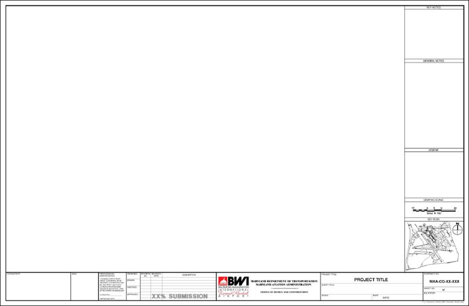
Figure 2-1 shows the standard MDOT MAA border at the time of this publication. Figure 5-1 shows the title block portion of the MDOT MAA border. The bubble call-outs in Figure 2-2 refer to Table 2-4, where each item is described. Consultants should use the standard border sheet that is available in AIRPortal under General > PEGS Reference Documents.
The standard border includes the following features:
Border
Title Block
Consultant ID Block
Drawing Field
P.E. Stamp Box
Notes
Legend
Key Plan
Graphic Scales
North Arrow
Plot Stamp (Full path name, User name, Date, Time)
Key Plan is to match appropriate MDOT MAA Airport and Project Location showing drawing layout.
MDE SF # when provided by MDE.
Project Title.
Contract No.
Scale (if applicable).
Date.
Sheet No.
Designed.
Drawn By.
Checked.
Any Revision No., Revision Dates and Revision Descriptions as necessary.
Professional Certification
The most current MDOT MAA-approved drawing formats, templates and seed files are stored in AIRPortal under General > PEGS Reference Documents. Consultants and sub-consultants have access to the most current resources to perform their services compliant with MDOT MAA’s current standards. Consultants are responsible to review the PEGS Reference Documents library to ensure they are using the most current versions.
Figure 3-1, Standard Border

Figure 3-2, Title Block
All borders shall include the following information with the exception of the key plan, which applies to plan sheets only:
|
ITEM |
BLOCK DESCRIPTION |
|
1 |
Consultant Name, Address, Logo |
|
2 |
Engineer’s P.E. Stamp |
|
3 |
Engineer’s Certification |
|
4 |
Initial Block |
|
5 |
Revision Date and Description Block |
|
6 |
Airport Logo and Name Block |
|
7 |
Project Title |
|
8 |
Sheet Title |
|
9 |
Key Plan |
|
10 |
Scale |
|
11 |
Date |
|
12 |
Contract Number |
|
13 |
Sheet Number |
Table 3-4, Drawing Title Block Descriptions
The following statement must be placed on all sheets that contain SSI as defined in the Code of Federal Regulations (49 CFR Part 1520). This statement should be placed in the area above the drawing title shown as item 6 in Figure 3-2 above. Individuals preparing or handling SSI, are required to read and abide by the terms and conditions in PEGS V2, Chapter 3.1.2 Electronic Deliverables Containing Sensitive Security Information (SSI), which define who can handle and how they should handle SSI.
Warning: This document contains Sensitive Security Information that is controlled under 49 CFR Part 15 and 49 CFR Part 1520. No part of this record may be disclosed to persons without a “need to know”, as defined in 49 CFR Part 15 and 49 CFR Part 1520, except with the written permission of the Administrator of the Transportation Security Administration or the Secretary of Transportation. Unauthorized release may result in civil penalty or other action. For U.S. government agencies, public disclosure is governed by 5 USC 552 and 49 CFR Part 15 and 49 CFR Part 1520.
3.4.1.4 Title Sheets
Figure 3-3 below, shows the standard title sheets for projects at both BWI and Martin State Airport (MTN). Consultants should use the standard title sheet that is available in AIRPortal under General > PEGS Reference Documents.
The most current MDOT MAA-approved drawing formats, templates and seed files are stored in AIRPortal under General > PEGS Reference Documents. Consultants and sub-consultants have access to the most current resources to perform their services compliant with MDOT MAA’s current standards. Consultants are responsible to review the PEGS Reference Documents library to ensure they are using the most current versions.
The following information will be included on all title/cover sheets:
Airport Logo and Name
Maryland Department of Transportation
Maryland Aviation Administration
Chief Engineer
MDOT MAA CONTRACT TITLE (assigned by MDOT MAA )
Contract No, MDOT MAA-CO-00-000 (assigned by MDOT MAA Office of Procurement)
AE Design Task Number
Construction Task Number (applicable to Comprehensive Construction Projects only)
Submission Name (e.g. 30% Design, Bid Documents, Conformed, Record, etc.) and date
Sensitive Security Information (SSI, as defined by 49 CFR Part 1520) statement as it appears below (applicable to document sets containing SSI).
Warning: This document contains Sensitive Security Information that is controlled under 49 CFR Part 15 and 49 CFR Part 1520. No part of this record may be disclosed to persons without a “need to know”, as defined in 49 CFR Part 15 and 49 CFR Part 1520, except with the written permission of the Administrator of the Transportation Security Administration or the Secretary of Transportation. Unauthorized release may result in civil penalty or other action. For U.S. government agencies, public disclosure is governed by 5 USC 552 and 49 CFR Part 15 and 49 CFR Part 1520.
Vicinity Map and Site Map.
1. The site map should include gridlines that conform to the grid layout defined in the MDOT MAA Naming and Addressing Standard.
2. The combined extent of the area covered by all sheets provided should be clearly indicated on the site map.
Consultant Name Block and Stamp Block
Signature Blocks Including Signature Line and Date Line for:
1. Airport Security
2. Fire Marshal and
3. MDOT MAA Division of Facilities Design
Drawing Index
1. Should additional space be required provide separate index sheet immediately behind cover sheet.
2. The comment ‘(contains SSI)’ should be added after the title of any documents listed in the Index of Drawings that contain SSI.
3. Project Title
4. Construction Contract Number
5. AIP No. (if applicable) [AIP No. is provided for federally funded projects and shall be obtained from the MDOT MAA Director of Capital Programs]
6. Site and Vicinity Maps are to match appropriate MDOT MAA Airport and Project Location
7. Index of Drawings (if space is insufficient to list all drawings, use second sheet for Index of Drawings)
8. Design Task Number
9. Construction Task Number (if applicable - this number generally applies to on-call construction contracts)
10. MDE SF No. (if applicable)
11. Index of Drawings.
12. Submission Type (30%, 60%, 90%, Bid, Conformed, Record, etc.)
13. Professional Certification
14. Date
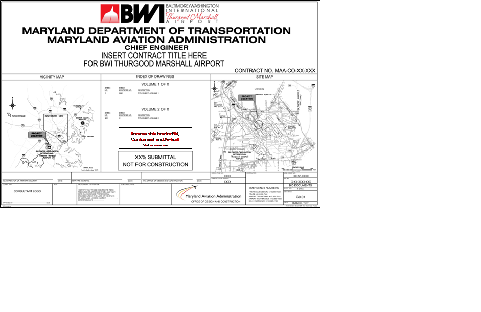
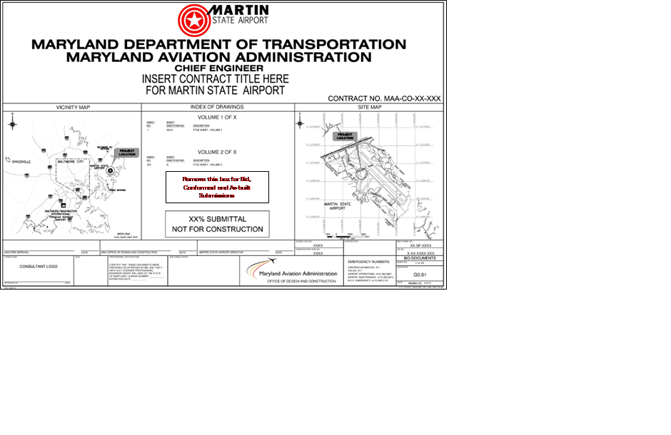
Figure 3-3, Title/Cover Sheet Layout Samples
Modifications to the standard cover sheet and border require prior approval of the Office of Engineering and Construction.
3.4.1.5 Drawing Numbering
The drawing sequence number for CAD drawing starts with an upper case letter specifying the discipline followed by a three digit sequential number, starting with 001 within each discipline code (i.e. C001, C002 …, C00n; A001, A002 … A00n). The discipline codes are listed in PEGS V1, Appendix 1D.1 Layer Development. Drawing numbering shall be consistent throughout the drawing set.
3.4.1.6 Arrangement of Drawings
The drawings in a construction drawing set are listed by discipline in Table 3-6, Construction Drawing Set.
Construction Drawing Sets
The drawings in Table 3-6 are commonly used in identifying a complete set of drawings for the construction of a new facility. Drawing sets for the construction of facility modifications must consist of a subset of the drawings listed in this table. Demolition drawings may be submitted under the Demolition discipline or under another discipline. Construction drawing sets shall be arranged by discipline in the following order, although the exact placement of demolition drawings can vary by project.
|
DISCIPLINE |
DRAWING CODE |
DESCRIPTION |
|
General |
G |
Cover, Index, Abbreviations, Symbols, Staging & Safety Plans |
|
General |
G |
Security Plan |
|
Real Estate/Lease |
R |
Property Boundaries And Legal Descriptions |
|
Civil |
C |
Demolition |
|
Civil |
C |
Legend |
|
Civil |
C |
Site |
|
Civil |
C |
Boring Log |
|
Civil |
C |
Under Slab Drainage |
|
Civil |
C |
Building Site Plan |
|
Civil |
C |
Grading Plan |
|
Civil |
C |
Utility Plan |
|
Civil |
C |
Details, Elevations And Sections |
|
Civil |
C |
Site Improvements |
|
Civil |
C |
Layout, Grading, Draining and Landscaping |
|
Civil |
C |
Structural Details |
|
Demolition |
D |
Removal of Existing Construction |
|
Hazardous Materials |
H |
Hazardous Materials |
|
Landscaping |
L |
Legend, Symbols and Abbreviations |
|
Landscaping |
L |
Irrigation Plan |
|
Landscaping |
L |
Planting |
|
Landscaping |
L |
Irrigation and Planting Details |
|
Architectural |
A |
Legend, Symbols and Abbreviations |
|
Architectural |
A |
Floor Plan |
|
Architectural |
A |
Reflected Ceiling Plan |
|
Architectural |
A |
Roof Plan |
|
Architectural |
A |
Elevations |
|
Architectural |
A |
Sections |
|
Architectural |
A |
Details |
|
Architectural |
A |
Millwork |
|
Architectural |
A |
Equipment |
|
Architectural |
A |
Furniture |
|
Interiors |
I |
Interior Building Elements |
|
Structural |
S |
Legend, Symbols And Abbreviations |
|
Structural |
S |
Structural Foundation Plan |
|
Structural |
S |
Framing and Decking Plan |
|
Structural |
S |
Roof Framing Plan |
|
Structural |
S |
Structural Details |
|
Structural |
S |
Structural Steel Grounding |
|
Structural |
S |
Erection Drawings |
|
Mechanical |
M |
Legend, Symbols And Abbreviations |
|
Mechanical |
M |
Equipment Schedule |
|
Mechanical |
M |
Elevations |
|
Mechanical |
M |
Generator and Fan Room Plan |
|
Mechanical |
M |
Chiller Room Plan |
|
Mechanical |
M |
Mechanical Room Plan |
|
Mechanical |
M |
Roof Plan |
|
Mechanical |
M |
Sections and Details |
|
Mechanical |
M |
Details |
|
Mechanical |
M |
Hot and Cold Piping Diagrams |
|
Mechanical |
M |
Miscellaneous |
|
Mechanical |
M |
Steam Piping Systems |
|
Mechanical - HVAC |
M |
Under Floor Plan |
|
Mechanical - HVAC |
M |
Floor Plan (Room Area) |
|
Mechanical - HVAC |
M |
Ceiling Plan |
|
Baggage Handling System |
Q |
General Notes, Legend and Abbreviations |
|
Baggage Handling System |
Q |
Floor Plans |
|
Baggage Handling System |
Q |
Enlarged Floor Plans |
|
Baggage Handling System |
Q |
Sections |
|
Baggage Handling System |
Q |
Details |
|
Baggage Handling System |
Q |
Controls |
|
Plumbing |
P |
Legend, Symbols and Abbreviations |
|
Plumbing |
P |
Foundation Plan |
|
Plumbing |
P |
Piping Plan |
|
Plumbing |
P |
Riser Diagram |
|
Plumbing |
P |
Sanitary Riser Diagram |
|
Plumbing |
P |
Storm Riser Diagram |
|
Plumbing |
P |
Roof Drain System |
|
Plumbing |
P |
Details |
|
Electrical |
E |
Electrical Demolition |
|
Electrical |
E |
Legend, Symbols and Abbreviations |
|
Electrical |
E |
Single Line Diagrams |
|
Electrical |
E |
First Floor Lighting Plan |
|
Electrical |
E |
Power and Communications Plan |
|
Electrical |
E |
Grounding Plan |
|
Electrical |
E |
Security Plan |
|
Electrical |
E |
Equipment |
|
Electrical |
E |
Motor Control Schematics |
|
Electrical |
E |
Miscellaneous |
|
Electrical |
E |
Details |
|
Electrical |
E |
Panel Schedules |
|
Electrical |
E |
Airfield Electrical Duct Bank Plan and Profile |
|
Telecommunications |
T |
Legend, Symbols And Abbreviations |
|
Telecommunications |
T |
1st Floor Communications Plan |
|
Telecommunications |
T |
Details |
|
Telecommunications |
T |
Manhole and Cable Diagrams |
|
Fire Protection |
F |
Legend, Symbols And Abbreviations |
|
Fire Protection |
F |
Sprinkler System |
|
Fire Protection |
F |
Fire Pump Location Plan |
|
Fire Protection |
F |
Alarm Systems |
|
Fire Protection |
F |
Fire Fighting Equipment |
|
Fire Protection |
F |
Stand Pipe System |
|
Z-Contractor |
Z |
Shop Drawings |
Table 3-5, Construction Drawing Set
3.4.1.7 Typical Sheets and Layouts for Construction Drawing Sets
The following sections provide examples of drawing sheets that shall always be included in a drawing set.
Cover Sheet
See Figure 3-3, Title/Cover Sheet Layout Samples and AIRPortal under General > PEGS Reference Documents for downloads.
Index Sheet
The index sheet shows a continuation of the drawing list from the title sheet, if required, all abbreviations used in the document set and a legend depicting all existing and proposed symbols. Reference contracts pertaining to the active task document are to be included in the provided attributed block. The consultant or sub-consultant should contact MDOT MAA’s Office of Engineering and Construction to assist in identifying this list of reference contracts and to obtain copies of the documents from the reference contracts. A sample of each standard Index Sheet is available in AIRPortal under General > PEGS Reference Documents.
The most current MDOT MAA-approved drawing formats, templates and seed files are stored in AIRPortal under General > PEGS Reference Documents. Consultants and sub-consultants have access to the most current resources to perform their services compliant with MDOT MAA’s current standards. Consultants are responsible to review the PEGS Reference Documents library to ensure they are using the most current versions.

Figure 3-4, Index Sheet Example
An example index sheets is shown in Figure 3-4, Index Sheet. The columns shown are for illustration only and may be adjusted to accommodate more or less of one type of information.
Other Sheets
MDOT MAA has developed standard General Notes sheets for airside and landside construction projects. These are available through the MDOT MAA Design Standards publication. The remainder of the drawing sheets are discipline specific. To provide an example of all such sheets is beyond the intent of this standard. View and download files at AIRPortal under General > PEGS Reference Documents.
3.4.1.8 MDOT/MDOT MAA Logo Art
MDOT MAA provides the following logos in electronic format for use in CAD documents. The following .jpg image files contain the color MAA, BWI, and MTN logos referenced by the standard contract drawings. The appropriate image files must be placed in the same folder as the standard contract drawings in order to appear when the drawings are opened in AutoCAD. They are accessible through AIRPortal under General > PEGS Reference Documents.
|
Figure 3.4a, MDOT_MAA Logo_Color_Large_Long.jpg
|
|
|
Figure 3.4b, BWI-Thurgood_Logo_Color_Long.jpg
Figure 3.4c, BWI-Thurgood_Logo_Color_Stacked.jpg
|
Figure 3.4d, MTN Logo Color.jpg |
3.4.1.9 Layers
For layer naming conventions, MDOT MAA has adopted the CAD LAYER GUIDELINES of the National CAD Standard (NCS), Version 5. Layers commonly used by MDOT MAA are listed in PEGS V1, Appendix 1D.1 Layer Development. Additional names as defined by the NCS shall be used as needed, in a manner that is consistent with their definitions. No other layers shall be used without prior written permission from MDOT MAA.
Sheet File (Paper Space) Layer Assignment
A sheet file is synonymous with a single sheet or page of a plotted CAD drawing file. A sheet file is a selected view or portion of referenced model files within a border sheet. The addition of sheet-specific information (e.g., text, dimensions, and symbols) completes the construction of the document. Table 3-7, Common Sheet File Layers, outlines layers that will be common in all sheet files in a set of construction drawings:
|
General Layers |
||
|
Name |
Description |
Color No. |
|
G-ANNO-DIMS |
Dimensions and Leaders |
5 |
|
G-ANNO-IDEN |
Identification Tags: Floor Id. #s; Room #s; Door #s; hardware group; Window #s; Equipment Id. #s; Furniture #s; Tenant Identification; Area calculations; Occupant or employee names; Elevation Id. #s; Component Id. #s |
7 |
|
G-ANNO-KEYN |
Key Notes |
7 |
|
G-ANNO-LEGN |
Legends |
4 |
|
G-ANNO-NOTE |
Notes |
7 |
|
G-ANNO-NPLT |
Construction Lines, non-plotting information |
8 |
|
G-ANNO-PATT |
Cross-hatching, patterns, poche |
5 |
|
G-ANNO-REDL |
Redline Annotations |
10 |
|
G-ANNO-REFR |
Reference Files |
7 |
|
G-ANNO-REVS |
Revisions |
4 |
|
G-ANNO-SCHD |
Schedules |
7 |
|
G-ANNO-SYMB |
Miscellaneous Symbols |
4 |
|
G-ANNO-TEXT |
Miscellaneous text and callouts with associated leaders |
7 |
|
G-ANNO-TITL |
Drawing Component Titles, Detail Titles, Section Titles, Elevations |
3 |
|
G-ANNO-TTLB |
Border and title block information |
2 |
Table 3-6, Common Sheet File Layers
Model File (Model Space) Layer Assignment
A model file contains the physical components or features that make up a building, facility, or site (e.g., columns, walls, windows, ductwork, piping, etc.). Both MDOT MAA and NCS layer names consist of a discipline designator, a major category and minor categories. Once the discipline designator, major and minor categories have been determined, a final portion of the layer name indicating status may be added. This describes to the user what the disposition is of the entities on that layer, and helps to determine if that layer should or should not be shown on a particular drawing sheet. Refer to PEGS V1, Appendix 1D.1.3 Status Indicators for common status indicators.
3.4.1.10 Text Styles/Fonts
The MDOT MAA standard fonts include “out of the box” fonts that ship with every installment of AutoCAD as well as Windows true type fonts. Any font not meeting this criterion must be submitted to the MDOT MAA Project Engineer for approval and inclusion in the project specific standard Font Library (.shx or .ttf) file.
All Text Styles shall use the naming convention, (font name) (_) (text height in decimal equivalent of inches) e.g. ROMANSR-R120
3.4.1.11 Text Justification
All annotation text shall be left justified.
3.4.1.12 Text Heights
The following text heights must be used on all drawings to ensure uniformity in the contract documents.
|
ENTITY |
PLOTTED TEXT HEIGHT (IN INCHES) |
|
Titles |
0.25 |
|
Subtitles |
0.175 |
|
Normal Text |
0.125 or 0.1 |
|
Notes, callouts etc. |
0.125 or 0.1 |
Table 3-7, Text Heights
3.4.1.13 Line Widths and Colors
In AutoCAD, each color represents a different line width when plotted. Although other methods exist, this is the accepted MDOT MAA Standard. It is preferable to control the line widths in a drawing by assigning a specific color to the layer, instead of assigning a specific color to a single element/entity (line, polyline, arc, etc.). The color of a single element/entity should be set to “BYLAYER”, so the layer’s color setting can be used to globally change all elements/entities on that layer, both in the model files and sheet files.
Each "sheet file" submitted to the MDOT MAA, must be able to be plotted in monochrome and still be legible with distinctions between lines types and other symbology readily apparent. To achieve this, the MDOT MAA Standard Pen Settings in Table 3-9, MDOT MAA Standard Pen Settings, should be used. Pen widths are specified for only the AutoCAD index colors. Colors 1-9 plot as solid lines, and colors 250-254 plot as screened lines. There is a pen table for both full size (ANSI D) drawings and half-size (ANSI B) drawings:
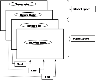
Table 3-8, MDOT MAA Full Size.ctb

Table 3-9, MDOT MAA Half Size.ctb
3.4.1.14 Line Types
The MDOT MAA standard linetypes include “out of the box” linetypes (these are linetypes that ship with every installment of AutoCAD) and linetypes defined in the NCS.
The most current MDOT MAA-approved drawing formats, templates and seed files are stored in AIRPortal under General > PEGS Reference Documents. Consultants and sub-consultants have access to the most current resources to perform their services compliant with MDOT MAA’s current standards. Consultants are responsible to review the PEGS Reference Documents library to ensure they are using the most current versions.
Any new linetypes created by a consultant must be submitted to the MDOT MAA Project Engineer for approval and inclusion in the project specific standard linetype (.lin) file.
It is preferable to control the linetypes in a drawing by assigning a specific linetype to the layer, instead of assigning a specific linetype to a single element/entity (line, polyline, arc, etc.). The linetype of a single element/entity should be set to “BYLAYER”, so the layer’s linetype settings can be used to globally change all elements/entities on that layer, both in the model files and sheet files.
3.4.1.15 Drawing Units
The units for all A/E/C drawings shall be U.S. Survey Foot (1200/3937 meters), inches and fractions of an inch, with the smallest fraction normally being 1/8" or as decimals. Dimensions of less than a foot must be shown in inches or fractions of inches, or as decimals inches.
3.4.1.16 Working Units, Coordinate Systems and Drawing Origins
Units should be selected according to the discipline of the drawing, architectural (feet and inches), engineering (feet and tenths), or decimal. References to feet in this document are specifically to the U.S. Survey Foot (1200/3937 meters).
All topography and topography related design including structural and architectural building footprints shall be submitted to, maintained by, and provided by MDOT MAA in accordance with the Survey Control Standards.
The lower left corner of all other drawings should be positioned at the Cartesian coordinate point of 0, 0, 0.
3.4.1.17 Externally Referenced Files
Externally referenced files are related DWGs that are referenced to the current (aka host) DWG to provide additional content. Referenced files can include title/borders, base map information, or other details not included but related to the primary drawing. Figure 3-5, Externally Referenced Files Example, illustrates the concept of how a sheet file drawing is composed using model/design and informational xref files.

Figure 3-5, Externally Referenced Files Example
Specific Use of AutoCAD Reference Files
All files referenced in the host file shall be included in the final drawing package. Nested or circular xref files are not allowed.
Reference files shall be added to all drawings using relative paths only. These paths do not include the drive letter and reflect the location of the reference file as it relates to the active file.
3.4.1.18 Patterning
The patterns (hatching) to be used on MDOT MAA drawings include only “out of the box” hatch patterns; customized patterns must not be used.
3.4.1.19 Dimensioning
Refer to the ANSI Y14.5M for additional dimensioning information not provided in this standard.
The distance from the object for the first dimension is 1/2" (0.5”) and each additional dimension is 3/8" (0.375”) further apart. See Figure 3-6, Dimension Directions and Spacing Example, and Figure 3-7, Dimension and Extension Line Spacing Example for dimension examples.
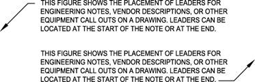
Figure 3-6, Dimension Directions and Spacing Example

Figure 3-7, Dimension and Extension Line Spacing Example
The following dimension guidelines shall apply:
1. Avoid crossing dimension lines.
2. Centerlines may be extended and used as extension lines.
3. Place longer dimensions outside of shorter ones.
4. Do not cover dimensions with patterns in sectioned areas.
5. Whenever possible, arrange dimensions so they can be read easily on one continuous line.
6. Dimensions are always placed on the drawing so that the text may be read from the bottom or the right.
7. Locate dimension lines so that they do not cross extension lines. If it is necessary to dimension at an angle, that angle should be in quadrant between the horizontal and vertical so text may be read between 0 and 90 degrees.
8. All text must be located above or centered on the dimension lines.
9. The location of text on the dimension line shall be consistent throughout the drawing set.
10. Fractions must be located on one line with a space between the whole inch and fraction.
11. Make fractions with a slant bar with numbers the same height as text, for example, 1/4".
12. All dimension and extension lines shall be created using the “Color 1” line weight.
13. Arrowheads and dimension text shall be created using the “Color 1” line weight.
14. All text shall be left justified per standard drafting standards.
Leaders
When a note or dimension cannot be placed close to an object, a leader may be used. A leader consists of a short horizontal line, an angled line and a terminator. When placing a leader to the left side of a note the horizontal line must be place in line with the top of the note. If the leader is on the right side, the horizontal line is placed at the bottom of the note, see Figure 3-8, Placement of Leaders Example. When a leader points to an object, the angled line must terminate with an arrowhead at its first object line. When the information refers to (applies to, or points to) a surface of an object, use a small filled dot or tilde (~). When the information refers to a bundle or grouping of wires or cables, use a lasso. An example is shown in Figure 3-9, Typical Leaders Example.
All leader lines and arrowheads shall be created using the “Color 1” line weight.
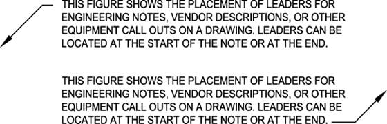
1. Figure 3-8, Placement of Leaders Example
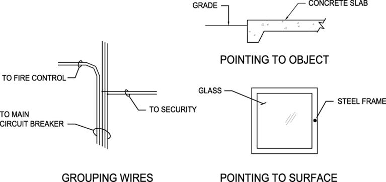
Figure 3-9, Typical Leaders Example
Arrowheads
Arrowheads denote termination of dimensions and leader lines and show direction. They must be filled, and must be the same size and style as the arrowheads used in other dimensions. Arrowhead size should be a 3:1 ratio for length to width, and in proportion to any associated text.
3.4.1.20 Symbols
Symbols used in drawings should comply with the NCS and all symbols used in a drawing must be indicated in a legend.
3.4.1.21 Drawing Subtitles
Subtitles must be used on drawings with more than one view or when sections or details are required for clarity and must also be used on drawings with a single view when title block information is inadequate and additional identification is required. Subtitles are always located below and centered on the view to which they apply, except for detail drawings where the title shall be located to the lower left.
Subtitles for plans, standard details, typical details, etc., which are not referenced in other views, consist of two lines. The first line shows the exact title of the view or detail and the second line indicates the scale of the view or detail, along with bar scale, see Figure 3-10, Standard Subtitle Annotation Example.
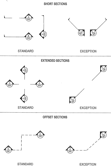
Figure 3-10, Standard Subtitle Annotation Example
3.4.1.22 Sections and Details
Sections must be drawn when additional clarification is warranted and details must be created whenever additional clarification is required and a section cannot readily be cut.
Sections
Sections must be drawn using the drafting standards shown in Figure 3-11, Standard Section Annotation Example. The three types of section indicators to be used are short sections, extended sections, and offset sections as shown in Figure 3-12, Section Types Example. All sections must be cut toward the top or left side of the drawing, except in unusual situations. In some cases, it may be necessary to cut a short section reading from the left, but this should be avoided if possible.
Sections must appear on the same drawing on which they are cut, if possible. If the section cannot be drawn on the same drawing, it must appear on a separate drawing reserved for sections. Under no circumstances are sections to be scattered indiscriminately throughout the set of drawings.
Section cuts shall be lettered in alphabetical order on each drawing. The letter in the top half of the circle marker must indicate the section letter. The alphanumeric number in the lower half of the circle marker must indicate the drawing on which the section is shown. Heavy dark lines located in the position where the section is cut must indicate the location of the cutting plane.
Offset sections may be used only when section clarity requires adjustment of a portion of the cutting plane. On all section cuts, the circle markers must be placed so they can be read from the direction of cut.
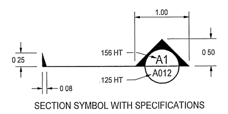
Figure 3-11, Standard Section Annotation Example
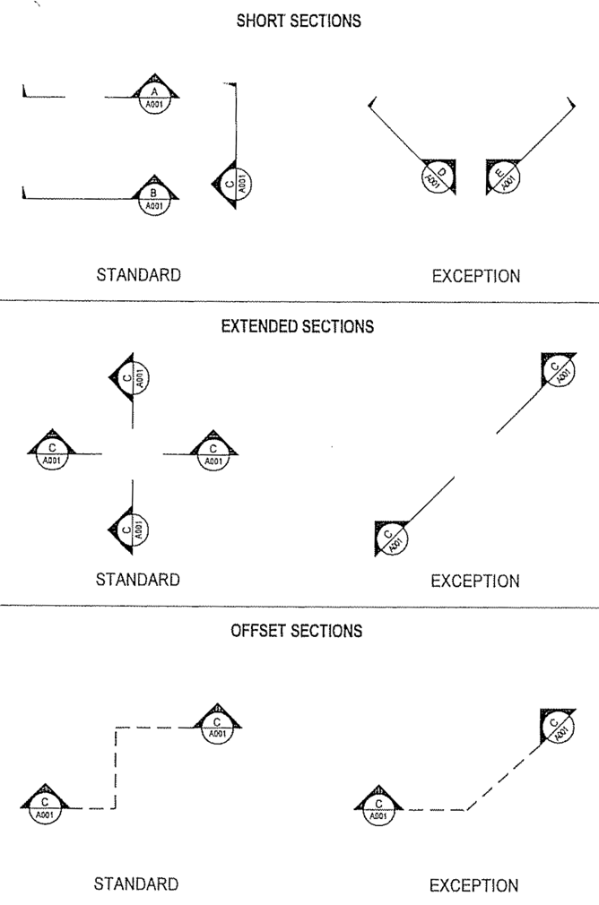
Figure 3-12, Section Types Example
Detail Drawings
The detail must be a section, a plan view, an elevation, or an enlargement. Details must have an alphanumeric (e.g. A1) designation in the upper half of the circle marker. When details are intermixed with sections and it would be difficult to locate a lettered detail on a drawing, the details must be numbered consecutively with the sections. The alphanumeric number in the lower half of the circle marker must indicate the sheet number on which the details reside (see Figure 3-13, Standard Detail Symbol Example).
When a detail appears more than once on the same drawing, extend a line off the detail, abbreviate the word typical (TYP), and indicate the quantity in parentheses.
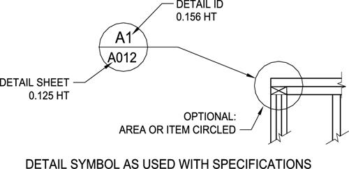
Figure 3-13, Standard Detail Symbol Example
3.4.1.23 Revision of Drawings
Changes to contract drawings must be clearly identified and tracked. The following sections outline the required methodologies for incorporating changes to the drawing set.
Required Revisions – Once a drawing has been approved and submitted as final, all subsequent changes shall be recorded as a revision.
Revision Methods – Revisions shall be made by the addition or deletion of information and the changes annotated on drawings.
Drawing Practices – When revising an existing drawing the most recently approved graphic symbols, abbreviations, layer naming requirements, and drawing practices, as documented in this standard, shall be used to incorporate changes or revisions.
Identifying Revisions on Drawings – All revisions shall be identified with a revision cloud and revision number within a triangle for addenda and a square for redline revisions. The revision number in the title block must correspond to the revision number in the drawing area where the change was made.
Revision Locations – The revision location is identified by the revision cloud and only additions or modifications are to be included within the revision cloud.
Revision Numbers – Revisions are to be identified by a sequential number starting at 1. Letters are not to be used for revision identification.
Multiple Changes – The same revision number shall identify all changes made to a drawing regardless of number of locations modified that are incorporated at the same time.
Revision Block – The revision block size and format shall conform to that in the standard border sheet provided. Only the five most current revisions shall be shown in the revision block and each revision shall be recorded in accordance with the following:
1. The identifying number pertaining to the revision shall be entered in the “REV” column.
2. The date the CAD file changes revision shall be entered in the “DATE” column.
3. A brief description of the change shall be entered in the “DESCRIPTION” column.
Redrawn or Replaced Drawings – Drawings are redrawn when standard drawings are converted to CAD or when there are extensive changes to a CAD file. The new drawing shall contain a note referencing the superseded drawing. The note shall be located above the revision block on the new drawing stating:
“THIS DRAWING SUPERSEDES DRAWING __________, REVISION___, DATED________.” Subsequent revisions to the new drawing shall start with the number 1, regardless of the revision number of the drawing being superseded. A note shall also be located above the revision block on the superseded drawing stating: “THIS DRAWING SUPERSEDED BY DRAWING __________, DATED __________.” The statements shall be in letters not less than .125 inches high.
3.4.1.24 Feature Drawing Rules
Geometric features are objects in drawings that represent specific objects in the real world such as an airfield light, utility conduit, building outline, or property boundary.
Allowable Geometry Types
There are three basic types of geometry (i.e., points, lines, and polygons) that are permissible in CAD drawings provided to MDOT MAA. Only one geometry type is allowed on layers that contain geometric features, as opposed to annotation or dimension layers. Only one type of geometry should be present on a single layer. The following geometry type definitions are used in accordance with ISO 19107 and in compliance with the Open GIS Consortium Level 0 Profile of GML Version 3.
Point: a single location represented by X and Y (and in some cases Z) coordinates on a reference coordinate system, as shown below in Figure 3-14. Blocks can be used to symbolize point features so long as the block is placed on the appropriate layer for that type of feature. The insertion point of the block should be placed at the correct geographic location of the feature. If blocks are used, no additional point object should be placed at the features location.

Figure 3-14, Example of a Point Feature
Line: straight line connections between two or more discrete locations represented by X and Y (and in some cases Z) coordinates on a reference coordinate system, as shown below in Figure 3-15. Note that line segments (i.e., a straight line connecting two points) and polylines (i.e., one or more connected line segments) are both included in this definition but that arcs (i.e., a curve joining two points) are not.
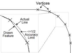
Figure 3-15, Example of Line Features
Polygons: A closed connection between three or more discrete locations represented by X and Y (and in some cases Z) coordinates on a reference coordinate system, as shown below in Figure 3-16. A closed polyline can also be used to represent a polygon.
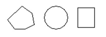
Figure 3-16, Example of Polygon Features
Complex Geometry Types: Arcs, circles, and ellipses should not be used to represent geographic features. These complex geometry types can be used in details, building faces, and other drawing components that are not intended to be represented in geographic space. This is intended to facilitate data exchange between software that processes these complex data types differently. These shapes may however be represented by polylines or polygons as appropriate. For example, if arcs are used in a CAD drawing, they must first be broken into a line with vertices placed at intervals that are sufficient to maintain the feature’s accuracy requirements.
Topology Rules
The placement of geometric features in juxtaposition to one another (i.e., next to, connected to, or on top of) is referred to as a topology. Topology rules establish requirements for the placement of features in relation to one another and in relation to features in other Feature Types. Unless stated otherwise, this standard requires the following topological rules:
Line Feature Types: Lines should contain one or more line segments with vertices placed at required intervals so the line feature does not stray from the actual feature by more than half the accuracy limit for that feature type, as shown below in Figure 3-17.
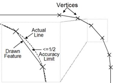
Figure 3-17, Placement of Vertices Along a Curve
Lines should begin and end at (snap to) vertices coincident (i.e., exactly at the same coordinate) with features (often point Feature Types) designed to join two or more linear features, as shown in Figure 3-18. An example is electrical conduit lines that are joined only at junction boxes and other similar point features. For lines not naturally joined by physical features (e.g., marking lines), beginning and ending nodes should be placed where an attribute or other property change occurs.

Figure 3-18, Coincident Line End Points
Lines should not fall short (i.e. have gaps) or extend beyond (i.e. have dangles) features they are intended to connect to. When lines are connected to features represented by blocks, the line should connect (snap) to the insertion point of the block and not to the outer edge of the block.
Polygon Feature Types: Polygons must always be closed, meaning all vertices must be shared by two adjacent line segments forming the edges of the polygon, as shown in Figure 3-19.

Figure 3-19, Example of Closed and Unclosed Polygons
Unless otherwise stated, polygons must not overlap other polygons on the same layer, as shown in Figure 3-20. This includes polygons placed on top of other polygons, as well as small overlapping splices because one or more vertices of adjacent sides are not matched. Polygons placed within (e.g., a ‘doughnut hole’) a larger polygon (e.g., the ‘doughnut’) which do not overlap are acceptable, because they describe a physically different space from the surrounding polygon.

Figure 3-20, Examples of Overlapping Polygons
Polygons must share vertices with adjacent polygons where the real-world features they represent are adjacent, as shown below in Figure 3-21. This rule applies to polygons in the same Feature Type as well as polygons of different but related Feature Types.
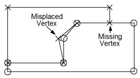
Figure 3-21, Placement of Vertices of Adjacent Polygons
Layering of Features
Features of the same type and geometry should be the only elements on any specific layer. Text and leaders relevant to feature on a layer should appear on a corresponding but different layer that complies with the layer naming conventions in this standard.
Relationship Between GIS & CAD Layers
MDOT MAA requires that CAD data be easily convertible into a GIS format to the extent feasible. To accommodate this exchange of data, a crosswalk between CAD and GIS layers has been developed and can be found in PEGS V1, Appendix 1D.4 Crosswalk Relationships.
3.4.1.25 Feature Attribution
In some cases, MDOT MAA requires that geometric features in CAD drawings include attributes such as size, material, and condition. These requirements will be defined in individual project statements of work. When MDOT MAA requires attributes, they should be attached to geometric objects in drawings via an object data table. If the same set of attributes are required for all features, a single object data table is preferred.
The attributes found in the object data table should align with attributes in MDOT MAA’s GIS Data Standard for the corresponding GIS layer. For example, points or block symbols on the C-RUNW-ENDP layer, which corresponds to the RunwayEnd GIS layer per the CAD-GIS crosswalk, should include attributes for the runwayEndDesignator, thresholdType, and others. In some cases, the values that can be entered into these attributes will be bound to a domain list. For example, the attribute thresholdType is bound to domain called CodeThresholdType, which allows the values of Normal or Displaced.
Note that the ability to define, enter and edit object data is limited to AutoCAD Map 3D or AutoCAD Civil 3D products. This software will be required to enter such values into DWGs where required by MDOT MAA.
Attribution is not the same as annotation.
3.4.1.26 Coordinate Tick Marks
Coordinate Tick Marks, also called Coordinate Ticks or Grid Ticks, are notations on a drawing marking specific coordinate locations. Coordinate Ticks allow drawings to be aligned with other drawings, with GIS or CAD data, or with GPS coordinates in the field.
In any MDOT MAA capital or CMAR project, or permit application, each plan view shall have three or more Coordinate Ticks, spaced a minimum of one hundred feet apart, showing coordinates in the Maryland State Plane coordinate system (see PEGS Volume 1 Chapter 4.5 Coordinate System for details). Coordinate Ticks shall be placed on coordinates divisible by ten feet; single-digit or decimal values such as 603841 or 1477025.8 are unacceptable. For plans showing larger areas, Coordinate Ticks shall be placed on coordinates divisible by the largest even increment possible given the confines of the plan limits, such as one hundred feet, two-hundred and fifty feet, five hundred feet, or one thousand feet.
Coordinate ticks should be placed in the view forming either a triangle or rectangle, as far apart as is possible within the confines of the plan view limits.
Figure 3.4.1.26 shows a Coordinate Tick on a typical plan view.
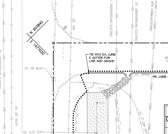
Figure 3.4.1.26 Typical Coordinate Tick Mark