3.5 Electronic Deliverables
3.5.1 General
MDOT MAA requires all submittals to be made electronically/digitally. Electronic deliverables shall be submitted in the same timeframe as hard copy deliverables.
All CAD drawing files MUST be delivered in AutoCAD DWG and PDF formats. The DWG files MUST be created with the approved software from the list provided in Section 3.1.4 Software Requirements of this standard. Additionally, all DWG submittals must be made utilizing the eTransmit function within Autodesk products. Instructions appear later in this chapter.
Project drawings produced using Autodesk Revit is optional, however, files must still comply with the standards described in this section. Drawings shall be submitted in their native revit format with the electronic deliverable in addition to the standard formats listed above.
All PDF files shall be created to allow printing but restrict editing by a third party. Each PDF should contain a single sheet drawing. Consultants will use the Standard Drawing File Naming Format shown in Section 3.5.1.2 Electronic File Preparation.
When submitting electronic contract documents to MDOT MAA, one sheet file representing each contract drawing shall be submitted in accordance with the MDOT MAA Design Standards. Each sheet file shall be ready to plot at full-size (1:1) in paper space. Layers must be controlled properly to reflect the document’s intended appearance. Use of drawing files with multiple layouts is permitted only in the case of cross sections.
3.5.1.1 Delivery Media
DWGs and any related documents or files shall be submitted via MDOT MAA’s AIRPortal Document Manager (ADM) application. Refer to Section 3.5.1.2.B, eTransmit Procedures. All electronic deliverables must be virus free.
3.5.1.2 Electronic File Preparation
Consultants shall deliver one eTransmit zip file containing all sheets, their unbound DWGs and their related files as gathered and presented by the eTransmit functionality. The eTransmit utility will be used to combine each AutoCAD file and its related support files such as raster images, external references, and fonts into a single zip file.
For the PDF version of contract drawings documentation submittals, each PDF file should contain only one contract drawing. The drawings should be organized and submitted in the proper sequence of the drawings set. Each file should follow the “Standard Drawing File Naming Format” as defined below.
-
Standard Drawing File Naming Format
|
Volume
Identifier
|
_
|
Sheet
Sequence
|
Insert
Identifier
|
_
|
Sheet
Identifier
|
_
|
SSI
Identifier
|
.
|
Format
Extension
|
2.
Figure 3-22, Standard Drawing File Naming Format
Volume Identifier: 2 character field should contain “V1”, “V2”, etc. Used only when drawing set is divided in multiple packets or “volumes”. Omit field and underscore if all drawings are included in one volume.
Sheet Sequence: 4-digit number starting with “0001.” Leading zeros are required. The number counts all sheets in the drawing set. In cases where there is more than one volume in a set, sheet sequencing shall be continuous through all volumes. The sheet sequence number for the last drawing of the set is equal to the total number of drawings in all volumes. For example, Volume 1 has ten drawings and Volume 2 is twenty drawings making the total number of drawings thirty. Volume 1 will be numbered V1_0001 through V1_0010; then Volume 2 will be numbered V2_0011 through V2_0030 which continues the number sequence from Volume 1 and ends at the number equaling the total number of sheets in the set. All drawings, including SSI-marked sheets and repeated sheets such as the Index of Drawings sheet, must be included in the total sheet sequence count.
Insert Identifier: Single letter characters used for inserting added drawings into an existing sequence. “A” is the first insertion. “B” is the second and so on, through “Z”. Where there are no inserted sheets, this field is omitted.
Sheet Identifier: Sheet number as shown in drawing title block. Follows existing CAD standards (Example: G0.0, E1.1, C1.0, etc.).
Sheet Title: Sheet title as shown as shown in drawing title block. Special characters such as “/”, “\”, “&”, “*” etc. are not permitted.
SSI Identifier: Insert the letters “SSI” to identify drawings that contain Security Sensitive Information for special handling. Omit field and preceding underscore if no SSI data present.
Format Extension: Application defined code (Example: dwg, dwf, pdf, etc.).
-
eTransmit Procedures
1. With a drawing open, choose File > eTransmit
2. In the Create Transmittal dialog box, click Transmittal Setups…
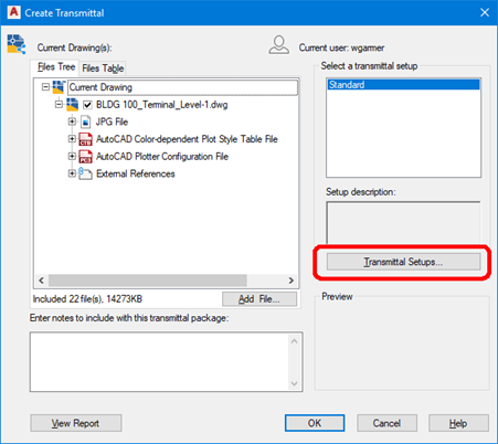
Figure 3-23, Create Transmittal Dialog Box 1
-
In the Transmittal Setups dialog box, click Modify… to modify the Standard setup
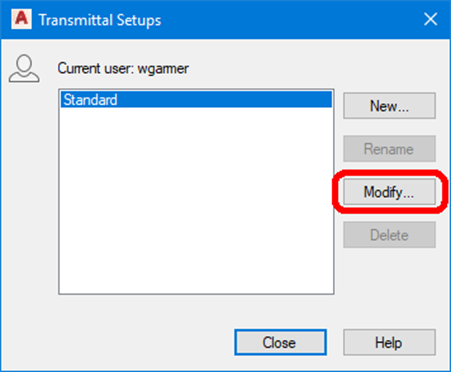
Figure 3-24, Create Transmittal Dialog Box 2
-
In the top section of the Modify Transmittal Setup dialog box, set the Transmittal Type and Location information.
1. In the Modify Transmittal Setup dialog box, choose a transmittal package type of .zip.
2. Under File Format, choose ‘Keep existing drawing file formats’. If the MDOT MAA Project Manager requires the file in an older version of AutoCAD, you can change this setting.
3. Under Transmittal file folder, choose the file folder where the transmittal file will be generated.
4. Set the Transmittal file name text box to ‘Prompt for a filename’
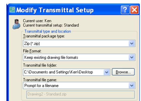
Figure 3-25, Modify Transmittal Dialog Box 1
-
In the bottom section of the Modify Transmittal Setup dialog box, set the Transmittal Options
1. Under Transmittal Options, choose the ‘Use organized folder structure’ radio button and supply your Source root folder (location where the project root tree structure resides on your server).
2. Click the radio button next to ‘Place all files in one folder’
3. Check the box next to ‘Include fonts’
4. Check the box next to ‘Set default plotter to ‘none’’
5. Name your transmittal setup for future use
6. Click OK to accept changes and return to the “CREATE TRANSMITTAL” dialog box.
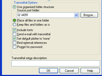
Figure 3-26, Modify Transmittal Dialog Box 2
-
In the Create Transmittal dialog box, ensure all necessary files are included in the Files Tree tab. This includes fonts, xref files, ASCII files, etc. Click Add File… to add additional files.
-
Click OK
-
When prompted for a file name, enter a file name that conforms to the naming convention defined in Section 3.5.1.2, Item A Standard Drawing File Naming Format.
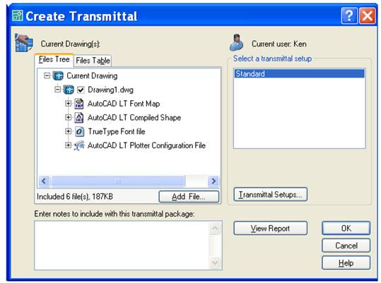
Figure 3-27, Create Transmittal Dialog Box 3
3.5.1.3 Documentation
All drawing packages submitted to the MDOT MAA shall include a transmittal letter containing the same information as on the external media label, and any special instructions for the restoring/transferring of files from the media.
3.5.1.4 Ownership
MDOT MAA shall have unlimited rights to all information and materials developed and furnished to the MDOT MAA and documentation thereof, reports and listings, and all other items pertaining to the work and services pursuant to this agreement including any copyright. Unlimited rights are rights to use, duplicate, or disclose data and information, in whole or part in any manner and for any purpose whatsoever without compensation or approval. The MDOT MAA will at all reasonable times have the right to inspect the work and will have access to and the rights to make copies of the above-mentioned items. All digital files and data, and other products generated shall become the property of the MDOT MAA.
3.5.2 Quality Assurance
This section lists the requirements for the inspection of drawings before they are submitted to MDOT MAA, and the engineering data quality assurance process that consultants and contractors must have in place.
3.5.2.1 Responsibility for Quality
The consultant is responsible for seeing that the electronic files are in compliance with MDOT MAA standards.
3.5.2.2 Quality Assurance Testing
Quality assurance testing carried out by consultants and contractors should include examining files for entities placed in the proper layer or level, proper drawing and plot parameters, title block is filled out and set correctly, and the drawing is free of unwanted entities. Where specific spatial accuracy is required, additional checking to ensure the accuracy of the data being submitted is required. Where attribution is required, attributes will be complete and will contain appropriate values. Procedures that MDOT MAA will use for acceptance testing and a recommended for consultant and contractor quality assurance are detailed in the MDOT MAA Data Quality Standard.
3.5.2.3 Engineering Data Quality Assurance Process
Unless otherwise specified in the contract or order, the contractor/supplier must have an effective quality assurance process for the detailed quality assurance and technical accuracy of all engineering drawings and associated lists to be supplied under the terms of the contract. The procedures of the quality assurance system shall assure the conformance of the engineering drawings and associated lists to the applicable contract provisions. The quality assurance system shall be documented, and subject to the approval of MDOT MAA's Project(Task) Manager.