7.7 Doors/Windows
7.7.1 Roll-up Doors
Fabric roll-up doors at “high hazard” locations are not permitted. Fabric roll-up doors do not provide a fire rating, and therefore provide a hazard when used at improper locations. “High hazard” applications include, but are not limited to, mechanical, switch gear, and electrical substation rooms. When fire rated doors are required, metal roll-up doors shall be specified.
7.7.2 Door Numbers
Refer to PEGS Volume 1, Section 2.4 Door Number Assignment.
7.7.3 Sterile Area Access Doors
In accordance with TSA mandate 5142-04-10A2, any proposal to increase the number of sterile area access doors (e.g. new construction) must be approved by TSA’s Federal Security Director.
7.7.4 Window Opaque
All projects at BWI Marshall shall be designed and specified per the following requirements wherever the work requires the obscuring or covering of existing exterior windows in the terminal facility:
A. Terminal A/B (Where Exterior Wall Panel or Spandrel Glass is WHITE)
1. Provide tinting of windows where required to opaque existing vision glass windows. Provide product as follows or an approved equal:
2. Lumar – Window Film – NRM W PS3
3. 3M – Fasara –San Marino
4. Product color is to closely match installed white spandrel glass.
5. Prior to installation, review glass surface and verify submitted film is compatible with surface.
6. Warranty – provide minimum ten year installation and material warranty.
7. Install window film as recommended by manufacturer and published guidelines from the International Window Film Association.
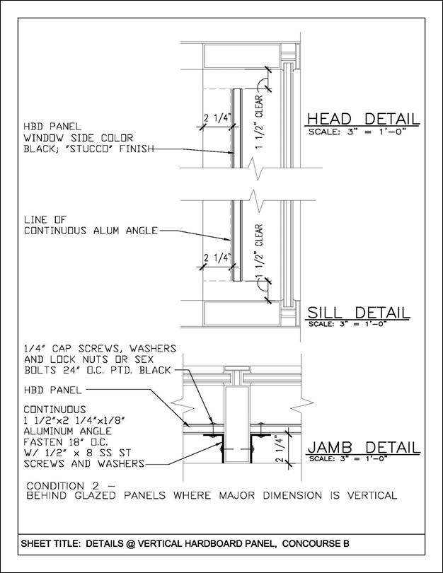
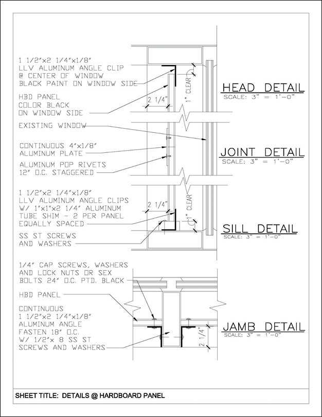
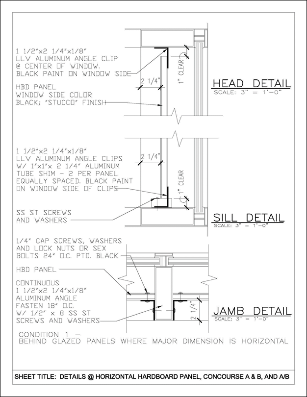
B. Terminal A/B and Concourses A and B (Where Exterior Wall Panel or Spandrel Glass is BLACK)
1. Provide infill panels where required to opaque existing vision glass windows. Provide hardboard panel (HBD) product as follows or approved equal.
a. Omega Foam - Ply HBD by Laminators Inc.
i. 0.013 “Stucco” aluminum face on window side with polyester paint finish; color black.
ii. 1/8” Tempered Hardboard Stabilizers.
iii. Polyisocyanurate Foam Core.
iv. Manufacturer’s standard white smooth finish on interior side of panels.
2. Install infill panels as detailed to interior of window frames wherever windows are required to be covered by tenant space requirements. See exhibits Horizontal Hardboard Panel, Concourse A & B, and A/B; and Vertical Hardboard Panel, Concourse B.
3. Provide manufacturer’s standard panel product warranty.
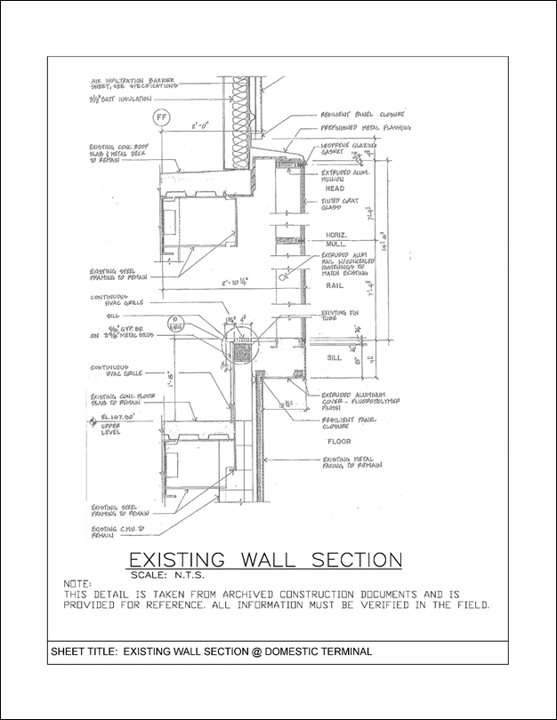
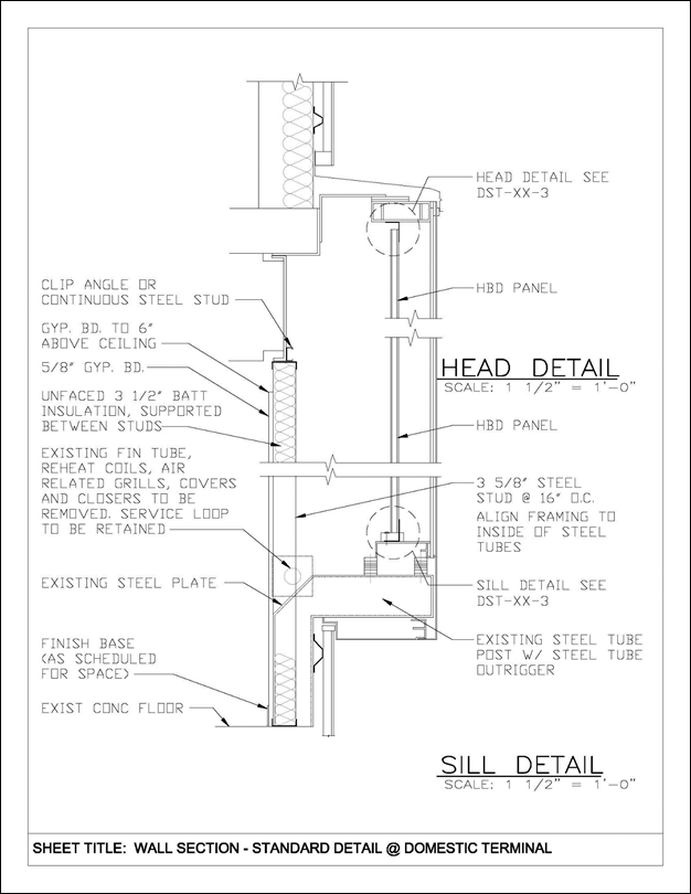
C. Terminals C and D
1. Prior to installing panels specified below, remove all reheat coils, fin tube radiation, covers, and other devices, and abandon piping back to the main line. Demolition must provide for continuation of existing downstream service. Temporary outages may be required by demolition, but the piping loop must be retained to service existing downstream units which remain.
2. Provide infill panels where required to opaque existing vision glass windows. Provide hardboard panel (HBD) product as follows, or approved equal.
a. Omega Foam - Ply HBD by Laminators Inc.
i. 0.013 “Stucco” aluminum face on window side with polyester paint finish; color black.
ii. 1/8” Tempered Hardboard Stabilizers.
iii. Polyisocyanurate Foam Core.
iv. Manufacturer’s standard white smooth finish on interior side of panels.
1. Install infill panels as detailed to interior of window jambs wherever windows are required to be covered by tenant space requirements. See exhibits for Wall Section – Standard Detain @ Domestic Terminal and Details @ Hardboard Panel.
2. Provide interior gypsum wallboard assembly of 3-5/8” 20 gauge steel studs with 5/8” Type X gypsum wallboard and un-faced batt insulation to interior of space as illustrated in the Wall Section – Standard Detail @ Domestic Terminal.
3. Provide panel manufacturer’s standard product warranty.
Consultant should refer to the following 5 exhibits.
7.7.5.1 General
Comply with the minimum requirements included herein for entrance doors to Adult Change Rooms. Entrance doors are to provide user privacy, and enhanced accommodation, which exceeds accessibility requirements included in ADA Accessibility Guidelines and ICC ANSI A117.1. In-swinging type doors are preferred.
7.7.5.2 Automatic Door Operator:
Provide low-voltage electro-hydraulic type automatic door operator. Door operation included in this Standard requires that automatic door operator comply with manual door closer reduced opening force.
A. Door Operator Characteristics:
The electro-hydraulic door operator, in simplest terms, is a motorized manual hydraulic door closer. Since it contains a manual closer, it can be adjusted to fully comply with the accessibility requirements for reduced opening force of a manual closer. Other features of the operator are to include the following
1. Obstruction detection on opening and closing cycles.
2. Adjustable door opening and closing force.
3. Adjustable hydraulic backcheck valve to cushion door speed if opened violently.
4. Three-position switch, ON/OFF/HOLD-OPEN, with cover plate to prevent tampering, if available from manufacturer specified.
5. Rigid type closer arm and slide track.
6. Tested to UL standards for automatic closing door, UL 10B and UL 10C; ADAAG-compliant; certified by BHMA to meet ANSI A117.1 and A156.19.
B. Door Operator Installation:
Door operators and track arms are to be through-bolted to hollow metal door frame heads and doors (wood or metal) with sex bolts. Heights of frame heads are to be designed to provide a minimum 4-bolt attachment of operator to frame. Refer to door and frame requirements 11.9.5.8 below.
C. Quality Control:
Installer must be trained and approved by automatic door operator manufacturer for installation and maintenance of product. Include testing and inspection of installation by an inspector certified by the American Association of Automatic Door Manufacturers.
D. Electric Strike:
An electric strike is necessary to permit the lockset latch to pass through the door frame when the automatic door operator is used, and the lockset lever is not turned. Door sequence of operation must be set to release the strike prior to activation of the door operator to protect the operator motor. Provide fail safe type strike.
E. Mortise Lockset:
Privacy mortise lockset with tubular lever of type that returns to door face; Best Access Systems interchangeable core lock cylinder (Ref: Chapter 7.5 Lock System) with thumbturn; indicator (Vacant/Occupied outside, Secure/Unsecure inside). Standard mechanical lockset is to be custom pre-wired at the factory with a switch, operated by turning the thumbturn or key. Lockset functions include the following:
1. Latchbolt by grip either side, unless outside grip is locked.
2. Outside grip locked or unlocked, and outside door operator press wall switch deactivated or activated, by key (outside) or thumbturn (inside).
3. Operating inside grip, closing the door, or using key unlocks outside grip, and activates outside press wall switch.
4. Inside grip always free, and inside press wall switch always activated.
5. Auxiliary latch deadlocks latch.
Lockset manufacturer will likely require that modification to mechanical lockset be reviewed and approved by their engineering department prior to release for fabrication. Coordinate with specified manufacturer(s) for procedure, and information to include in door hardware specifications.
F. Continuous Hinge:
Provide geared aluminum, edge-mount (mortise), continuous hinges for adult change room doors equipped with automatic door operators. Hinge may be electrically modified or prepared for power transfer hinge required for electrified mortise lockset.
G. Miscellaneous Door Hardware:
Provide miscellaneous door hardware required for project, including boxed power supply, kickplates, saddles, wall stops, and similar items.
H. Hardware Finishes:
Provide standard MDOT MAA-approved door hardware finishes and base metals.
I. Doors and Frames:
Hollow metal doors and frames to receive automatic door operators are to be fully welded, and internally reinforced to receive surface-applied door hardware. Reinforce frame heads with channel type reinforcing for full height of frame head and depth of frame. Reinforce frame hinge jamb and door hinge edge full height for continuous hinges. Where wood doors are used, coordinate door blocking requirements with door manufacturer(s) to ensure adequate reinforcing (blocking) is specified for door hardware.
J. Hardware Set:
The following is a sample door hardware set and sequence of operation. Note: This is NOT a standard specification. Consultant shall tailor the hardware set(s) to suit individual project requirements.
Sample Door Hardware Set and Sequence of Operation
1. Basis of Design Manufacturers: Names of the following basis of design manufacturers are abbreviated in the Schedule as indicated:
a. Best Access Systems; Div. of Stanley Security Solutions, Inc. (BAS).
b. Corbin Russwin Architectural Hardware; an ASSA ABLOY Group company (CR).
c. HES, Inc.; an ASSA ABLOY Group company (HES).
d. McKinney Products Company; an ASSA ABLOY Group company (MCK).
e. Norton Door Controls; an ASSA ABLOY Group company (NOR).
f. Pemko Manufacturing Co.; an ASSA ABLOY Group company (PMC).
g. Rockwood Manufacturing Company (RMC).
h. Securitron Magnalock Corporation; an ASSA ABLOY Group company (SMC).
2. POWER-OPERATED OPENINGS
HW-01 M x M
Door Nos. AT213, Dx201
|
Item |
Description |
Mfr |
BHMA |
|
1 continuous hinge |
MCK-25HD x 83" |
MCK |
628 |
|
1 power transfer hinge |
EL-CEPT |
SMC |
630 |
|
1 wiring harness |
ElectroLynx QC-C1500P (power xfer-junction box) |
MCK |
--- |
|
1 electrified lockset (privacy) |
ML2068 x M92 x M105 x M19VN x LWA 24VDC |
CR |
630 |
|
-- indicator (vacant-occupied) |
|
|
--- |
|
1 wiring harness |
ElectroLynx QC-CXXX x lgth. (pwr xfer to lockset) |
MCK |
630 |
|
1 mortise cylinder |
1E74 |
BAS |
626 |
|
1 electric strike (fail safe) |
1006 x 1000-KM x 2004 x 2005 x 24VDC |
HES |
|
|
1 wiring harness |
ElectroLynx QC-C1500P (strike-junction box) |
MCK |
--- |
|
1 door operator |
6010 x 120VAC x 668S |
NOR |
689 |
|
2 press wall plate switches |
505 |
NOR |
630 |
|
1 kickplate |
10" x 2" LDW x 0.050" 4BE CSK |
RMC |
630 |
|
1 mop plate |
4" x 1" LDW x 0.050" 4BE CSK |
RMC |
630 |
|
1 wall stop |
409 (gray) |
RMC |
630 |
|
1 threshold (AT213 only) |
190 drilled for countersunk fasteners |
PMC |
Alum |
|
1 set seals |
S88 BL x DOWxDOH |
PMC |
--- |
|
1 power supply (above ceiling) |
BPS-24-1 |
SMC |
--- |
3. Sequence of Operation
a. Entry to the restroom by rotating the corridor side lever or by use of the corridor side press wall switch.
b. Corridor side press wall switch to activate the electric strike and then the automatic door operator.
c. Person entering the restroom rotates the indicator turn piece locking the corridor side lever and deactivating the corridor press wall switch.
d. Rotating the restroom side lever unlocks the corridor side lever and reactivates the corridor side press wall switch via the request for exit (RX) switch.
e. Use of the restroom side press wall switch activates the electric strike and then the automatic door operator.
f. Use of the restroom side press wall switch reactivates the corridor side press wall switch and with the closing of the door unlocks the corridor side lever.
K. Maintenance and Occupancy Adjustment:
Prior to including in project specifications, review with MDOT MAA any requirements for the Installer to return to perform post Substantial Completion maintenance and occupancy adjustment for the automatic door operator.
L. Demonstration and Training:
Include in project specifications for MDOT MAA Maintenance personnel.