11.3 Power Distribution System and Equipment
Below outlines the requirements for 13,800-480 volt electrical substations.
A. All equipment and installations shall be in accordance with the National Electrical Code (NEC) per edition approved and specified in the Maryland Model Performance Code.
B. All equipment locations shall be coordinated with the MDOT MAA Office of Engineering & Construction.
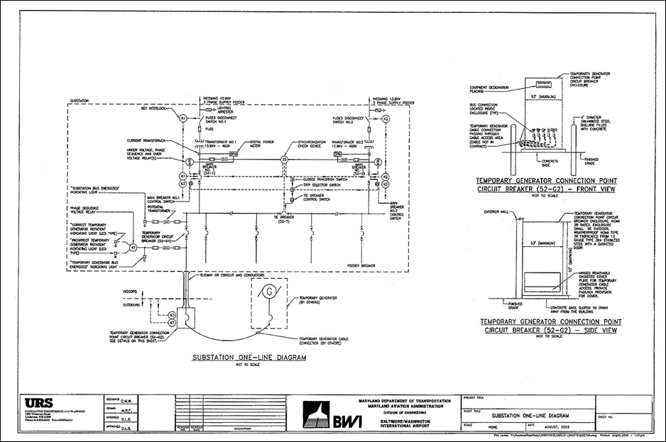
C. Substations shall be 13,800-480 volt, secondary selective configuration consisting of two primary (13,800 volt) feeders, two primary fused load interrupter switches, two power transformers, two secondary (480 volt) main circuit breakers, one tie breaker, and feeder breakers. All current carrying parts of the substation and related components shall be copper. Each substation shall be supplied by one North feeder and one South feeder originating from switchgear supplied from the BWI Marshall North and South substation respectively. Refer to Substation one-line diagram and the substation sequence of operation details for additional information. The current BWI Marshall medium voltage one-line diagram is included on the following pages.
D. The secondary main and tie circuit breakers shall be electrically operated draw-out type low voltage power circuit breakers or insulated case circuit breakers.
E. The feeder circuit breakers shall be manually operated draw-out type low voltage power circuit breakers, insulated case circuit breakers or molded case circuit breakers mounted in continuous metal enclosed switchgear or switchboard enclosure(s).
F. All substation short-circuit ratings shall be adequate for the combined available fault current contribution due to secondary closed transition switching. The available fault current shall be calculated for the moment that both secondary main breakers and the tie breaker are simultaneously closed and both transformers are energized from their primary source.
G. Ground fault protection shall be provided for all substation 480 volt circuit breakers including secondary main circuit breakers, tie breaker and all feeder breakers. Ground fault protection for 3 phase, 4 wire, solidly ground systems shall utilize current transformer (CT) sending for all phase and neutral conductors. Three (3) phase underground systems shall include a ground fault sensing and indication system.
H. Substations shall include a semi-automatic secondary closed transition switching scheme that allows for momentary simultaneous closing of both secondary main circuit breakers and tie circuit breaker for maintenance switching purposes. The closed transition scheme and associated components shall be designed and manufactured by the substation equipment manufacturer and designed specifically for this application. All components shall be integral to the substation. Refer to Substation one-line diagram and the substation sequence of operation details for additional information.
The consultant shall contact MDOT MAA maintenance personnel to see if any operating problems have occurred recently with closed transition operation at existing substations. If so, the consultant shall request that BGE perform a circulating study. The consultant shall make recommendations based on the results of the study.
The consultant shall contact BGE to see if any changes have been made that could affect the synchronization of incoming feeders and closed transition operation. If so, the consultant shall request that BGE perform a circulating study. The consultant shall make recommendations based on the results of the study.
Substation One-Line Diagram
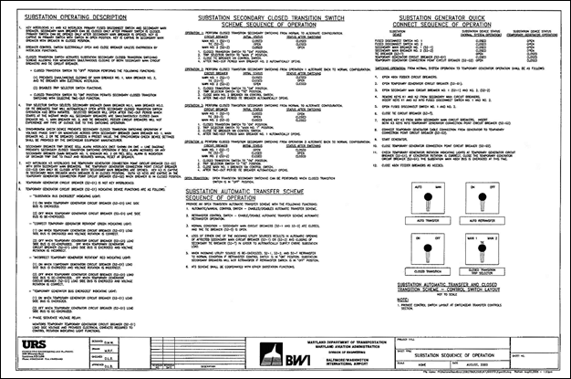
Substation Sequence of Operation
I. Substations shall include a secondary automatic transfer scheme that will automatically open one secondary main breaker and close the tie breaker in order to transfer all load to one primary feeder if abnormal voltage is detected on one of the two incoming substation primary feeders. Since there is an automatic transfer on the primary feeders to the substations, the automatic secondary transfer should incorporate time delays of sufficient length to allow the primary transfer to occur prior the secondary transfer. Refer to Substation one-line diagram and the substation sequence of operation details for additional information.
J. Substations shall include an emergency power quick connect system which includes a permanent connection point for a temporary electric generator in order to supply temporary power to the entire substation in the event of a complete substation power outage. The quick connect system shall include a temporary generator circuit breaker (52-G1) (located within the substation), temporary generator connection point circuit breaker (52-G2) (located outdoors, remote from the substation at an area easily accessible to the temporary generator), feeder from 52-G1 to 52-G2, and control system. The location of the temporary generator connection point enclosure shall be approved by the BWI Marshall Office of Airfield Operations and Security, as well as the Office of Facilities Maintenance. Refer to Substation one-line diagram and the substation sequence of operation details for additional information.
Circuit breaker 52-G1 and 52-G2 shall be manually operated. Circuit breaker 52-G1 and 52-G2 and the feeder shall have a rated ampacity equal to the substation main circuit breakers.
The temporary generator connection point circuit (52-G2) shall be installed in a pad-mounted enclosure of sufficient size and configuration to allow for temporary generator cable connections. The enclosure shall have the following options: NEMA 3R 12-gauge type 304 stainless steel construction, gasketed door, front accessible only, padlock provision, key interlock, internal heater (with thermostat and internal control power transformer), internal hinged dead front door (that allows breaker to be operated with no possible access to energized parts), temporary generator cable access area, and number of cables. The entire enclosure shall be rated NEMA 3R while-in-use when temporary generator cables are connected and operational. All components of the temporary generator connection point circuit breaker shall be specifically designed for this purpose and manufactured by the circuit breaker manufacturer or by the circuit breaker manufacturer factory authorized field service organization. An 8-1/2” x 11” aluminum sign attached to outside of the enclosure shall be installed with the following wording: “Substation _____ Generator Connection.” The name of the substation shall be filled in the blank space.
Attach a 10” x 4” self-adhesive engraved, laminated acrylic sign 1/8” thick to the exterior of the quick connect enclosure stating the phase rotation for connecting a portable generator. This sign shall include the wording in white text (size 3/8”) with a red background stating,
SUBSTATION ____ (Blank to be filled in with substation number)
QUICK CONNECT CABINET
CONNECT GENERATOR AS FOLLOWS:
CABINET LEAD COLORS: B O Y
GENERATOR LEAD COLORS: B O Y
Quick connects that have a phase rotation of C-B-A shall have the leads swapped so the generator temporary connection will follow an A-B-C phase rotation and shall include a sign inside the quick connect enclosure with the same specifications as the exterior sign and with the wording,
SUBSTATION ____ (Blank to be filled in with substation number)
QUICK CONNECT CABINET
PHASE A AND C HAVE BEEN SWITCHED
TO MATCH THE PHASE ROTATION
OF SUBSTATION _____ (Blank to be filled in with substation number)
Placards shall not overlap or cover existing signage on the equipment required by code. Samples of the exterior and interior quick connect placards have been included in Section 11.3.2.4.
K. Contract documents shall require performance of a short-circuit and coordination study during construction to establish settings for all new adjustable system protection devices. All new devices shall be selectively coordinated with existing devices and operating schemes including but not limited to, overload/short-circuit protection and automatic transfer schemes.
L. Contract documents shall require furnishing and installation of permanently attached engraved instruction placards including substation one-line diagram and all substation sequence of operations. Locate on placard at substation interior wall with an emergency lighting fixture with integral battery back-up in close proximity. Locate one placard on the inside of the temporary generator connection point circuit breaker enclosure.
M. Contract documents shall require furnishing and installation of a framed wall-mounted one-line diagram for the substation and the entire downstream distribution system. Locate with substation room.
11.3.2 Medium Voltage Electrical Phasing and Rotation (BWI Marshall only)
This section details the electrical phasing and rotation conditions for the BWI Marshall medium voltage electrical distribution system.
11.3.2.1 Medium Voltage Electrical Phasing and Rotation Background
The BWI Marshall Airport medium voltage distribution system is a three-phase system. The phases are labeled A, B and C in accordance with industry standard practices. System phase rotation must be consistent where multiple power sources are available for the following reasons: (1) for system identification and safety purposes, (2) to provide correct system rotation, and (3) to allow for the use of alternate distribution system configurations made possible by using Airport tie circuit breakers.
The term rotation refers to the order that the phases reach their maximum instantaneous line-to-neutral voltage value. There are two possible system rotations, ABC (positive sequence) or CBA (negative sequence). The rotation of the system determines the direction that a three-phase motor will spin when connected to the system. A three- phase motor connected to an ABC system will rotate in the opposite direction as compared to a CBA system. This is particularly important for HVAC and other three-phase motor equipment, since the rotation of the equipment is based on the electrical connection. The figure below shows the vector diagram for each of the two system phase rotations.
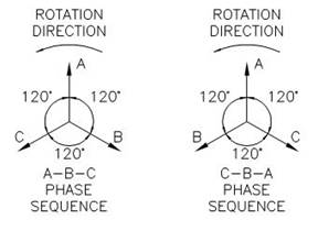
Two-system Phase Rotations
The existing medium voltage distribution system at BWI Marshall is shown in the following Airport Wide Phase Rotation Drawing with the Sheet Title “Single Line Diagram with Phase Rotation”. The single line diagram shows the power distribution from the primary of each power transformer located in the BWI Marshall North and South substations through the three 13.8 kV switchgears and to 480 V substations. The phase rotation at each switchgear and substation is shown on the Single Line Diagram.
The Table titled “Switchgear, Substation and Quick Connect Switches-Phase Rotation” summarizes the phase rotation for each switchgear, substation and quick connect cabinet at BWI Marshall Airport. The actual phase rotation shown for the electrical equipment in this Table was measured and verified in 2014.
The BWI Marshall system has adopted labeling and color coding for all 480 VAC conductors as an ABC rotation, where at 480 VAC, 3-phase equipment, phase A is color coded Brown, Phase B is color coded Orange and Phase C is color coded Yellow, following the B-O-Y conventional nomenclature. As an example of how the color coding is implemented at BWI the color coding of the power conductors for substations ST-TU and A1 are as follows:
Substation ST-TU has a phase rotation ABC, and the color coding of the substation feeder conductors on the load side of the substation breaker looking into the front of the breaker is left terminal lug, Brown, center terminal lug, Orange and right terminal lug, Yellow. The motors connected from this substation will follow the connections Phase A to Phase A, Phase B to Phase B and Phase C to Phase C. The color coding of the connection of these feeder conductors at the motor will be the same as at the substation.
In the case of Substation A1, which has a CBA rotation, this requires that in order for a three phase motor to turn in the correct rotation, the power wiring connection at the motor will have the A and C phase conductors switched. The color coding for the feeder conductors on the load side of the substation breaker looking into the front of the breaker will be left terminal lug, Brown, center terminal lug, Orange and right terminal lug, Yellow. The color coding of the connection of these feeder conductors at the motor will be the same as at the substation. The correct motor rotation will be accomplished by switching the A and C phase motor leads, where motor lead phase A will be connected to feeder conductor phase C and motor lead phase C will be connected to feeder conductor phase A.
11.3.2.2 Power Distribution System Design
The Consultants and Contractors shall consider the phase rotation differences that exist within the BWI Marshall Airport electrical power distribution system, particularly for Projects where equipment is powered from substations that do not have matching phase rotations.
The electrical power system designs that are performed at the BWI Airport North and South substations will require that the phase rotation remain consistent with that already established. The existing phase labeling shall remain and the consultant shall contact BGE at 410-291-3156 to coordinate all work at the North and South substations.
11.3.2.3 Generator Connections
AC Generator electrical phase sequence must match plant and utility electrical phase sequence. When three-phase temporary generators are used on the BWI Marshall Airport distribution system, the generator will be connected to the quick connect breaker conductors in an ABC rotation. The following Table, “Switchgear, Substation and Quick Connect switches – Phase Rotation” shows that the quick connects for substations A1, B1, B2 and ST-BC have a rotation CBA. In order to keep the temporary generator connections consistent for all of the quick connects at BWI Marshall Airport, the A and C phase leads from the quick connect breaker for the A1, B1, B2 and ST-BC quick connect breakers have been switched. Temporary generator rotation shall be electrically tested by the Contractor prior to connecting to the BWI Marshall system. Generators connected to BWI Marshall 13.8 kV – 480 VAC unit substation emergency power quick connect systems shall be tested for proper rotation using the voltage phase sequence relay and associated generator rotation indicating light that is permanently installed on the quick connect breaker in most substations. A substation quick connect sequence of operation placard is required by the MDOT MAA Substation Standard (Chapter 11.3.1 Substations) to be located at the substation and on the temporary generator connection point circuit breaker. This placard explains the use of the quick connect scheme including the generator rotation indicating light.
11.3.2.4 Electrical Systems Identification Placards
Placards with phase rotation information are installed at all switchgears, substations and quick connect switches at BWI Airport. The Consultant shall include phase rotation placards as required by these Standards for new switchgears, substations, and quick connect switches as described below. Placards shall not overlap or cover any existing signage or labeling on the electrical equipment as required by code.
A. Switchgears
The Consultant shall include phase rotation placards as required by these Standards for new switchgear at BWI Marshall Airport. The Consultant shall note in the Contract Documents to: “Attach a 6” x 3” self-adhesive engraved, laminated acrylic sign 1/8” thick to the exterior of switchgear stating the phase rotation. This sign shall include the wording in white text (size 3/8”) with a red background stating,
SWITCHGEAR ____ (Blank to be filled in with Switchgear number)
PHASE ROTATION
A-B-C (OR C-B-A AS VERIFIED)
B. Substations
The Consultant shall include phase rotation placards as required by these Standards for new Substations at BWI Marshall Airport. The Consultant shall note in the Contract Documents to: “Attach a 6” x 3” self-adhesive engraved, laminated acrylic sign 1/8” thick to the exterior of the substation stating the phase rotation. This sign shall include the wording in white text (size 3/8”) with a red background stating,
SUBSTATION ____ (Blank to be filled in with Switchgear number)
PHASE ROTATION
A-B-C (OR C-B-A AS VERIFIED)
C. Quick Connect Switches
The details for the quick connect placards both exterior and interior (where required) are as described in Chapter 11.3.1 Substations, Item H.
Sample templates for each of the placards described above are included in the following pages.
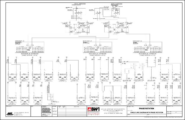
Single line diagram with phase rotation
|
SWITCHGEAR, SUBSTATION AND QUICK CONNECT SWITCHES PHASE ROTATION |
||||
|
SUBSTATION |
FED FROM SWITCHGEAR/ AS INDICATED |
MEDIUM VOLTAGE FEEDER NUMBER |
PHASE ROTATION |
QUICK CONNECT PHASE ROTATION |
|
A1-NORTH |
3 |
N33 |
CBA |
CBA * |
|
A1-SOUTH |
3 |
S33 |
CBA |
CBA * |
|
B1-NORTH |
3 |
N34 |
CBA |
CBA * |
|
B1-SOUTH |
3 |
S34 |
CBA |
CBA * |
|
B2-NORTH |
3 |
N35 |
CBA |
CBA * |
|
B2-SOUTH |
3 |
S35 |
CBA |
CBA * |
|
PG-1-NORTH |
3 |
N32 |
ABC |
NO QUICK DISCONNECT |
|
PG-1-SOUTH |
3 |
S32 |
ABC |
NO QUICK DISCONNECT |
|
ST-TU-NORTH |
3 |
N32 |
ABC |
ABC |
|
ST-TU-SOUTH |
3 |
S32 |
ABC |
ABC |
|
ARFF |
3 |
N38 |
ABC |
NO QUICK DISCONNECT |
|
UP-1-NORTH |
2 |
N28 |
ABC |
ABC |
|
UP-1-SOUTH |
2 |
S28 |
ABC |
ABC |
|
UP-2-NORTH |
2 |
N26 |
ABC |
ABC |
|
UP-2-SOUTH |
2 |
S26 |
ABC |
ABC |
|
UP-3-NORTH |
2 |
N25 |
ABC |
ABC |
|
UP-3-SOUTH |
2 |
S25 |
ABC |
ABC |
|
UP-4-NORTH |
2 |
N25 |
ABC |
NO QUICK DISCONNECT |
|
UP-4-SOUTH |
2 |
S25 |
ABC |
NO QUICK DISCONNECT |
|
PG-2-NORTH |
2 |
N27 |
ABC |
ABC |
|
PG-2-SOUTH |
2 |
S27 |
ABC |
ABC |
|
ST-AB-NORTH |
3 |
N36 |
CBA |
NO QUICK DISCONNECT |
|
ST-AB-SOUTH |
3 |
S36 |
CBA |
NO QUICK DISCONNECT |
|
ST-BC-NORTH |
3 |
N36 |
CBA |
CBA * |
|
ST-BC-SOUTH |
3 |
S36 |
CBA |
CBA * |
|
DY-1-NORTH |
1 |
N11 |
ABC |
ABC |
|
DY-1-SOUTH |
1 |
S11 |
ABC |
ABC |
|
DY-2-NORTH |
1 |
N16 |
ABC |
ABC |
|
DY-2-SOUTH |
1 |
S16 |
ABC |
ABC |
|
D-1-NORTH |
1 |
N16 |
ABC |
ABC |
|
D-1-SOUTH |
1 |
S16 |
ABC |
ABC |
|
NT-D-NORTH |
1 |
N13 |
ABC |
ABC |
|
NT-D-SOUTH |
1 |
S13 |
ABC |
ABC |
|
RW 15R PUMP STA. |
2 |
N24/S24 |
CBA |
NO QUICK DISCONNECT |
|
E-1-NORTH |
1 |
N15 |
ABC |
ABC |
|
E-1-SOUTH |
1 |
S15 |
ABC |
ABC |
|
E-2-NORTH |
1 |
N17 |
ABC |
ABC |
|
E-2-SOUTH |
1 |
S17 |
ABC |
ABC |
* The quick connect breaker feeder conductors are labeled and color coded with A-phase breaker connection as C-phase and C-phase breaker connection as A-phase
Switchgear, substation and quick connect switches phase rotation 1
|
SWITCHGEAR, SUBSTATION AND QUICK CONNECT SWITCHES PHASE ROTATION |
||||
|
SUBSTATION |
FED FROM SWITCHGEAR/ AS INDICATED |
MEDIUM VOLTAGE FEEDER NUMBER |
PHASE ROTATION |
QUICK CONNECT PHASE ROTATION |
|
NT-CT-NORTH |
1 |
N12 |
ABC |
ABC |
|
NT-CT-SOUTH |
1 |
S12 |
ABC |
ABC |
|
B-3-NORTH |
3 |
N31 |
CBA |
NO QUICK DISCONNECT |
|
B-3-SOUTH |
3 |
S31 |
CBA |
NO QUICK DISCONNECT |
|
B-4-NORTH |
3 |
N31 |
CBA |
NO QUICK DISCONNECT |
|
B-4-SOUTH |
3 |
S31 |
CBA |
NO QUICK DISCONNECT |
|
C-1-NORTH |
1 |
N14 |
ABC |
ABC |
|
C-1-SOUTH |
1 |
S14 |
ABC |
ABC |
|
AIRFIELD LIGHTING-NORTH |
1 |
N14 |
ABC |
ABC |
|
AIRFIELD LIGHTING-SOUTH |
1 |
S14 |
ABC |
ABC |
|
SWITCHGEAR 1 |
34.5 KV NORTH SUBSTATION |
NT1 |
ABC |
NOT APPLICABLE |
|
SWITCHGEAR 1 |
34.5 KV SOUTH SUBSTATION |
ST1 |
ABC |
NOT APPLICABLE |
|
SWITCHGEAR 2 |
34.5 KV NORTH SUBSTATION |
NT2 |
ABC |
NOT APPLICABLE |
|
SWITCHGEAR 2 |
34.5 KV SOUTH SUBSTATION |
ST2 |
ABC |
NOT APPLICABLE |
|
SWITCHGEAR 3 |
34.5 KV NORTH SUBSTATION |
NT3 |
CBA |
NOT APPLICABLE |
|
SWITCHGEAR 3 |
34.5 KV SOUTH SUBSTATION |
ST3 |
CBA |
NOT APPLICABLE |
Switchgear, substation and quick connect switches phase rotation 2
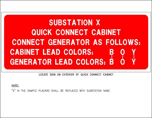
Sample placard for exterior of quick connect cabinet
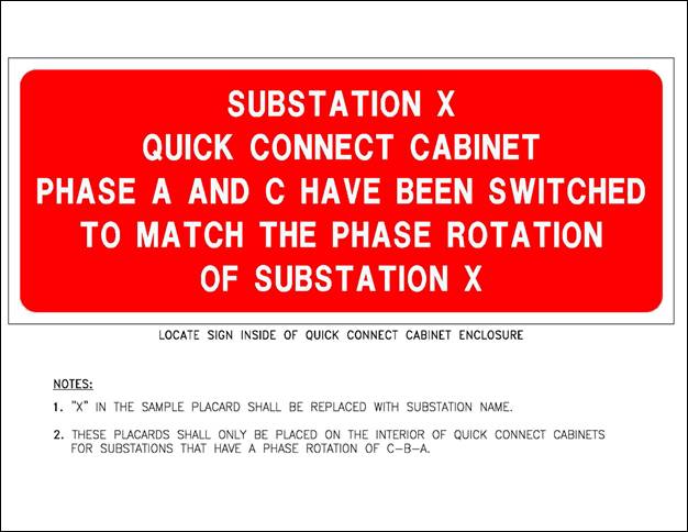
Sample placard for interior of quick connect cabinet
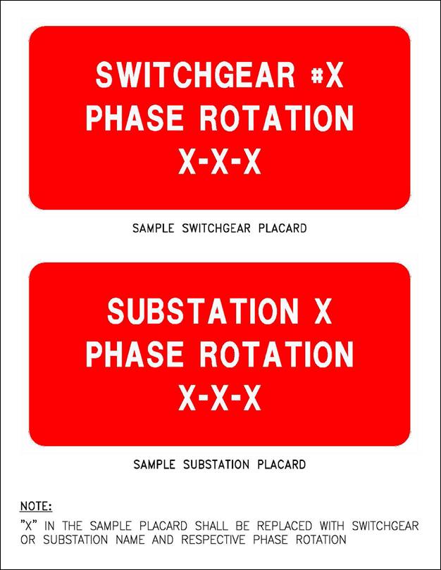
Sample placard for switchgear and substations