12.2 Exterior Lighting
12.2.1 Apron Lighting
All lightpoles and fixtures shall be specified based on aesthetics, design parameters, and replacement/maintenance considerations. Consultants shall match existing products when modifying and/or expanding existing facilities. A list of lamps that are kept in stock is available for inspection by consultants in the Office of Architecture. In addition, all designs shall be coordinated with the MDOT MAA’s Resident Architect in the Office of Architecture for aesthetics.
Consultants shall provide MDOT MAA’s Resident Architect and the Office of Facilities Maintenance with cut-sheets on every light fixture and lamp proposed for MDOT MAA projects prior to final design for their review and approval.
Exterior lighting on the airfield ramp shall meet the performance required by latest FAA AC 150/5300-13 Appendix 5. The FAA AC 150/5300-13, Appendix 5 states, “The area light beams must be directed downward and away from runway approaches and control towers. Shielding of the lights may be needed to minimize unwanted glare. Area light spread should cover all aircraft service areas uniformly. Refer to Illuminating Society of North America (IES), Recommended Practice for Airport Service Area Lighting, for additional guidance on apron lighting.” The use of Light Emitting Diode (LED) type lamps in fixtures shall be specified for new and where practical for upgrade/replacement apron lighting as long as the criteria specified in the IES recommended practice for airport service area lighting are met.
Lamination levels must be uniform and consistent. The consultant shall provide the contractor with limitation chart/curves for each lightpole proposed or to be modified as part of the bid documents.
Each pole shall bear an identification tag (engraved on aluminum plate) which shall list the manufacturer, model number, date of manufacture, and date of installation.
Heights of the poles should match existing for all reconstruction and retrofit projects. Consultants shall coordinate each lightpole installation(s) with and submit an Airport Zoning Application to MDOT MAA’s Office of Planning and comply with all State and Federal regulations. The consultant is fully responsible to check Part 77 for all lightpoles proposed or to be modifies. Lightpole height (including and lightning rods) shall not penetrate any navigational surfaces, i.e. FAR Part 77. If penetration is unavoidable, Federal Aviation Administration approval must be acquired. Refer to Volume 5, Section 2.2 FAA Requirements for Proposed Development.
The consultant must also check for any glare or line of sight issues when designing and locating lightpoles.
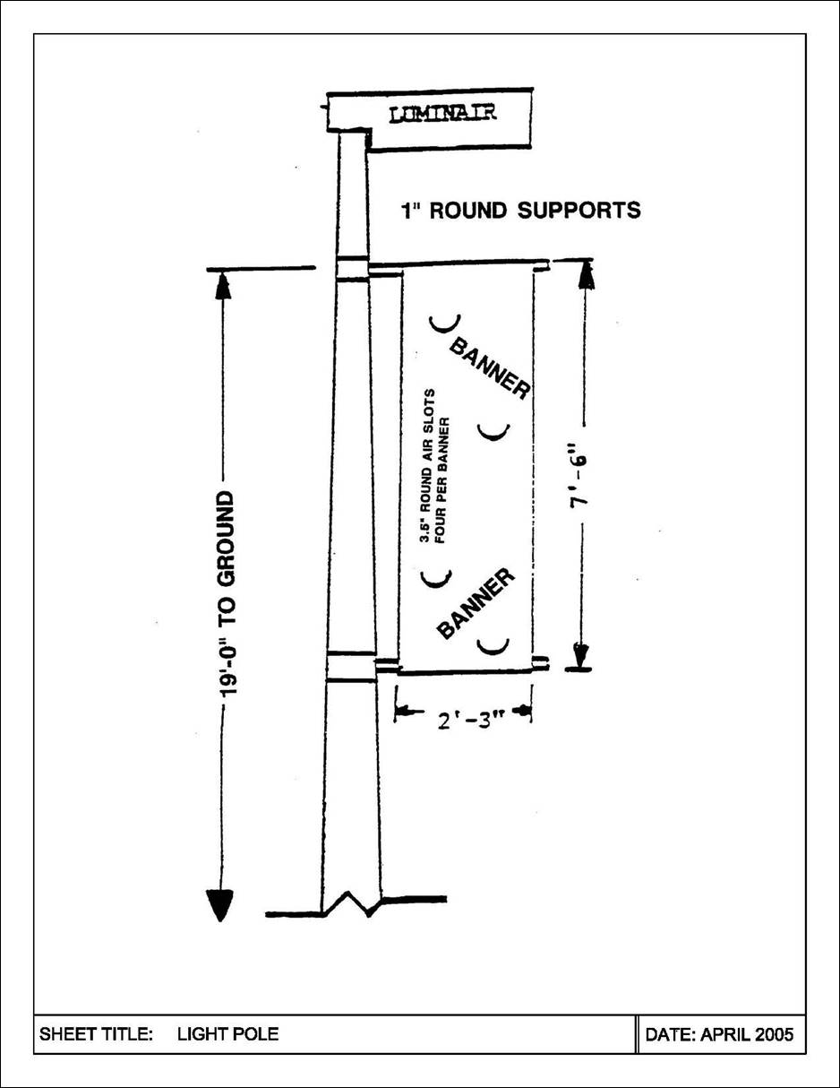
The consultant shall design the lightpoles to accommodate installation of banners on lightpoles, if requested by MDOT MAA. The consultant must inquire from the MDOT MAA Project Manager for any banner provisions and/or if any banners will be attached to the lightpoles.
Lightening protection and design must meet the current IES standards.
Color shall be black and smooth, unless otherwise approved by MDOT MAA’s Resident Architect in writing. Arms, luminaries, and all other attachments shall be provided in matching color.
12.2.1.1 Apron Lightpole Lowering Devices
All apron lightpoles installed at a height above 35 feet shall be designed and specified to include lowering devices for luminaries and their mounting assemblies. The height shall be measured from finished grade to top of lightpole mast, excluding lightning rod.
An external portable winch unit shall be used to lower the luminaire assembly down to the pole base for servicing.
A. Lowering Device Specification Requirements:
1. The lowering device shall be designed per the current American Association of State Highway and Transportation Officials (AASHTO) standards.
2. Comply with AASHTO LTS (Standard Specifications for Structural Supports for Highway Signs, Luminaries and Traffic Signals). Verify current edition used by MDOT MAA.
3. Lowering device light fixtures and lightpoles shall be manufactured and tested as one system and be provided and warranted by one manufacturer. Hoist cables for lowering device shall be stainless steel aircraft type, internal to lightpole, and factory installed.
4. A power outlet for testing of luminaries in the lowered position shall be provided.
B. Portable Winch Unit and Transformer Requirements to be specified:
1. For projects consisting of three (3) lightpoles or more, the contractor shall provide two (2) portable winch units. MORI forms must be prepared and submitted by the consultant.
2. For projects consisting of two (2) lightpoles or less, lightpoles shall be by the same pole manufacturer currently used at BWI Marshall and/or MTN Airports. This will eliminate the need for providing a new portable winch unit. Consultant shall coordinate with Procurement for the need of a sole source justification for the lightpole(s).
3. Portable winch units shall be 120-volt and be provided with wired remote controller, with cabling length of 15 feet minimum.
4. Transformer for portable winch unit shall also be portable, totally enclosed, permanent, primary and secondary, twist-locking plug connectors on pigtails to match pole-base power outlet and winch plug.
5. Primary of transformer shall be rated at the lighting-circuit voltage; secondary shall be rated at the voltage of the portable winch unit (120-volt).
12.2.2 Airfield Lighting and Visual Aids Systems and Fixtures
12.2.2.1 Light Fixtures
A. Light Emitting Diode (LED) type lamps in fixtures shall be specified for new airfield lighting projects at BWI Marshall and MTN Airports because of longer lamp life and lower energy consumption. ADB airfield lighting fixtures shall be used as the basis of design.
B. All fixtures used on BWI Marshall or MTN lighting projects shall be FAA approved types, with the type of lamp specified by the Consultant. Fixtures shall be certified under the Airport Lighting Equipment Certification Program described in FAA AC 150/5345-53, latest edition, and shall be of a type listed in Appendices 3 and 4 of the AC. Updates to the AC Addendum list of FAA approved fixtures are made periodically. Consult the FAA Advisory Circular web page to search for the most recent edition of FAA AC 150/5345-53 and to obtain the latest Addenda.
The Consultant shall include within Technical Specification L-125, “Installation of Airport Lighting Systems”, the applicable FAA approved fixtures listed in the most recent edition of FAA AC 150/5345-53.
C. The current FAA AC 150/5345-53 Addendum list has added a special designation for LED equipped fixtures. The fixture type now has an (L), following the last letter after the L- number designation to indicate an LED lamp is required. Example:
L-850A uses an incandescent lamp
L-850A (L) uses an LED lamp
In-pavement light fixtures shall be specified to be Class 2, Style 3. The class and style designation must be indicated in the Contract Documents. Class 2 indicates that the light fixture is constructed to accommodate base mounting. The Style 3 fixture is defined as having a maximum height of ¼ inch above finished grade and is intended to prevent damage to in-pavement light fixtures during snowplowing operations.
D. LED light and incandescent sourced lights shall not be mixed in a run of fixtures. Do not insert a series of LED lights within a length of incandescent lights, unless there is a change in direction. Every effort shall be made by the consultant to minimize transitions from one type of light to the other.
E. LED lights shall be specified without heaters unless the consultant is otherwise advised by the MDOT MAA Project Manager of a project specific requirement.
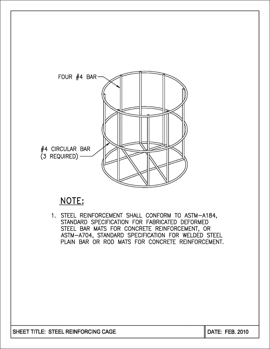
F. Steel reinforcing cages shall be provided on all in-pavement lights installed in both asphalt and concrete pavements. Steel reinforcing cages shall be in accordance with the Steel Reinforcing Cage detail. Steel Reinforcing Cage detail is attached to this section.
12.2.2.2 Lockout / Tag-out for Airfield Lighting for S-1 Series Plug Cutouts
All S-1 series plug cutouts shall be the lockable type. The following is the specification for the S-1 series plug cutout:
A. SERIES PLUG CUTOUT TYPE S-1. S-1 series plug cutouts shall be lockable, individually keyed with two keys, capable of carrying 20 Amperes, and shall have four contacts that close the circuit between the regulator and series lighting loop. The body shall be constructed of high strength plastic. The series plug cutout shall be protected against arcing. Porcelain bodies shall not be used.
12.2.2.3 Airfield Lighting Cable
A. Cables for Airfield Lighting Circuits shall be FAA L-824, 5kV, Type B cable with EPR (Ethylene Propylene Rubber) insulation and CPE (Chlorinated Polyethylene) Jacket. Underground cable shall conform to the requirements of FAA AC 150/5345-7 or latest edition, be provided by an FAA certified manufacturer and conform to the following additional specifications:
1. Cable shall be insulated and jacketed copper, #8 AWG, 7 strand (19 strand is acceptable).
2. Cable shall be single conductor, suitable for direct burial and/or raceway installation in wet conditions and shall be rated for a minimum 90° C for continuous service and130° C, for short circuit conditions.
B. Available Manufacturers: Certified L-824, 5kV, Type B cable manufacturers are listed in FAA AC 150/5345-53 or latest edition, and shall be listed in the current Addendum to Appendices 3 and 4. Updates to the Addendum list of FAA approved cables are made periodically. Consult the FAA Advisory Circular web page to search for the most recent edition of FAA AC 150/5345-53 and to obtain the latest Addenda.
C. There may be lead times of up to 16 weeks for cables, thus phasing of deliveries, contract completion time, and/or advance ordering should be considered by the consultant.
D. Permanent wiring shall be placed in conduit.
12.2.2.4 Airfield Lighting Cable Identification Tags
Consultants shall include the following information on the contract documents:
A. Identification tags shall be provided for each cable entering and/or leaving manholes, handholes, junction boxes, and light fixture cans.
B. All tags shall be plastic “phenolic” tags with colors as shown in the table below.
C. Two heavy-duty UV resistant black nylon ties shall be used to secure each tag to the cable.
|
Identification |
Tag Color |
Engraved Letter Color |
|
Primary Distribution |
Red |
White |
|
Runway Edge |
White |
Black |
|
Controls |
Black |
White |
|
Taxiway Edge or Centerline |
Blue |
White |
|
Runway Touchdown and Centerline |
Yellow |
Black |
|
FAA and Communication |
Green |
White |
|
Secondary Power |
White |
Red |
|
Spare Wire |
Orange |
White |
Additionally, cable identification tags shall be in accordance with the Cable Identification Tag detail. Cable Identification Tag detail is provided attached to this section.
12.2.2.5 Airfield Lighting Fixture Identification Tags
Fixture identification is maintained by MAA’s Office of Geospatial and Asset Management. Consultants must coordinate with Office of Geospatial and Asset Management no later than 100% submittal level to receive the proper identification number for new fixtures.
12.2.3 Landside Lighting (Parking and Roadways)
All light poles and fixtures shall be specified based on aesthetics, design parameters, and replacement/maintenance considerations. Consultants shall match existing products when modifying and/or expanding existing facilities. A list of lamps that are kept in stock is available to Consultants in the Office of Architecture. New parking lots and roadways shall be designed with LED pole mounted light fixtures. In addition, all designs shall be coordinated with the MDOT MAA’s Resident Architect in the Office Architecture for aesthetics.
Consultants shall provide MDOT MAA’s Resident Architect and the Office of Facilities Maintenance with cut-sheets on every light fixture and lamp proposed for MDOT MAA projects. LED fixtures shall be considered for all new areas and existing area upgrades where practical.
Light poles shall be round tapered aluminum poles with steel anchor bolts, transformer base, 2” x 4” handhole and a smooth black finish. Poles shall meet the performance of #RTA30.
Luminaries shall meet the performance of Holophane (Mongoose LED) cast aluminum housing, LED light engines with L70 greater than 100,000 hours, 5000K color temperature, 15,000-36,000 lumen output, luminaries with 5-3/4” arms and smooth black finish, and DLC qualified. Existing luminaries that are to be matched are 250W, 400W, or 1000W, HPS at 277V with a separate grounding wire.
Each pole shall bear an identification tag (engraved on aluminum plate) which shall list the manufacturer, model number, date of manufacture, and date of installation.
The need to install banners on light poles shall be coordinated with MDOT MAA’s Project Manager and the Office of Facilities Maintenance. Light poles, banner supports, and foundations shall be designed for banners, when required by MDOT MAA. The banner supports and hardware shall be coordinated with and approved by the Office of Facilities Maintenance. Harmonics shall be considered for lighpoles with banners.
Notwithstanding; FAA Part 77, heights of the poles should match existing for all reconstruction and retrofit projects. Consultants shall coordinate each light pole installation(s) with and submit an Airport Zoning Application to MDOT MAA’s Office of Planning & Real Estate and comply with all Local, State and Federal regulations. Light pole design shall not penetrate any navigational surfaces, i.e. FAR Part 77. If penetration is unavoidable, Federal Aviation Administration approval must be acquired (Refer to Volume 5, Section 2.2 FAA Requirements for Proposed Development.)
Parking lot concrete foundation heights shall extend a minimum of 2-1/2 feet above finished grade to resist vehicle impact.
Color shall be black and smooth, unless otherwise approved by MDOT MAA’s Resident Architect. Arms, luminaries, and all other attachments shall be provided in matching color.