13.1 Building Automation System
Building Automation System (BAS) for the BWI Marshall Airport shall be provided as outlined herein and according to the referenced Specifications located in Appendix 2D - Standard Specifications and guidelines described below.
The existing BWI Marshall Airport Building Automation System (BAS) is a Johnson Controls (JCI) Metasys system incorporating JCI legacy N2 protocol (old system) and BACnet MS/TP (New system). All current and future BAS modifications and additions must be performed by an authorized factory branch of Johnson Controls and will be required to communicate through the BWI Marshall Airport BAS site director which is a JCI Metasys ADX server.
The existing BAS system currently communicates on both Arcnet and Ethernet. Only minor modifications or additions will be performed with the JCI N2 protocol, except for remote facilities. Programming and modifications to the existing Person Machine Interface (PMI) archive and Network Integration Engine (NIE), and ADX server must be performed by persons regularly employed by Johnson Controls. BAS modifications or additions of size, such as additions of multiple HVAC systems or units, are required to communicate on the BWI Marshall Airport Ethernet through a JCI Network Automation Engine (NAE) or JCI Network Control Engine (NCE) on BACnet MS/TP at a baud rate of 38400. All work must be performed by an authorized representative of Johnson Controls, and any available software updates must be identified during design, so updates occur as part of the execution of the project.
The old version of BAS is based on N2 protocols and covers majority of the Airport BAS system.
The new BAS system is a BACnet, Web-Based, JCI Metasys system that was installed in 2009.
The server that serves the BACnet, Web-based controls, is located in the MAC Building. A combination of one Application and Data Server (ADS), four Network Integration Engines (NIE’s) and one Network Automation Engine (NAE) are major components of the server. The ADS provides 25 simultaneous access on the BWI Marshall Airport Ethernet system. Four Operator’s Work Station (OWS) are also located in the MAC Building.
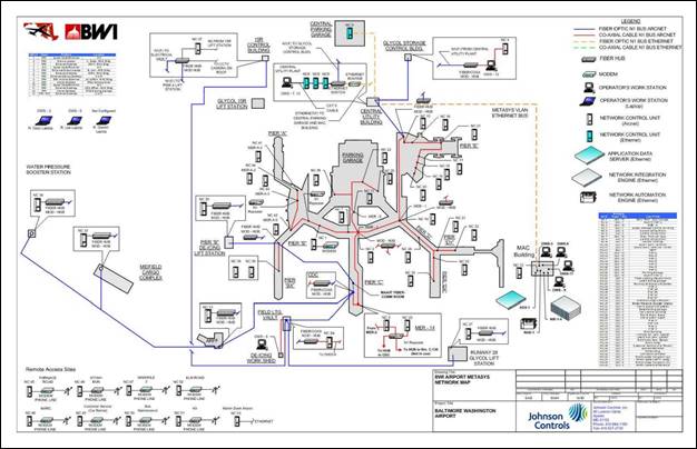
Refer to Metasys Network Map at BWI Marshall Airport detail on the following page for all existing controls and communication network.
The NIE integrates the old Metasys N2-based BAS into the new generation of technology that includes the internet, Information Technology (IT) and enterprise level global communication.
Metasys Network Map
All new controls shall be BACnet MS/TP direct digital controls as manufactured by Johnson Controls, except for remote facilities. A minimum of one Network Automation Engine (NAE) shall be installed as a Web-based extension to the existing Metasys ADX server network.
The old NC system shall be removed for major renovations where required and replaced with new NAE system. A major renovation is defined as a project that involves modification to the source component(s) of an HVAC system such as an air handler or central plant modification. Minor renovations involve the sub-systems or terminal units such as the VAV boxes, unit heaters, convectors, fan coil units, and space reheats. Each application needs to be explored for availability of BACnet network near the project location to identify the most cost effective approach, and impact on future projects.
New controls shall be designed and installed to meet the project specific requirements, MDOT MAA standards and sequence of operation. All new or updated software shall be installed in control units and operator workstations. Connect and configure equipment software to achieve sequence of operation.
Remote Facilities: There are several remote buildings and facilities that communicate with the existing BWI Marshall BAS (METASYS) by dial-up modem and they cannot be upgraded to the new system. These facilities are; Furnace Road, Stony Run, Manhole 2, Elm Road, MARC, Customer Service (Car Rental), Bus Maintenance, and K9. These facilities shall be handled separately, on a case-by-case basis and upgraded when a proper line of communication and network is available.
Ventilation shall be based on Demand-Controlled Ventilation (DCV), using CO2 sensors. DCV shall be based on the indoor CO2 level, compared with outside CO2 level, to make adjustment to the rate of outside air to the building. CO2 sensors shall be installed in spaces, return air duct, supply air duct as required and outside as a reference point to the inside level of the CO2. Minimum outside air shall be provided for pressurization, exhaust systems, and to meet non-human pollutant levels as required. Refer to Chapter 13.1.2 Existing Demand-Controlled Ventilation (DCV) Software for a sample of DCV program/ software description.
Airflow Measuring System shall be Thermal Dispersion type. Refer to Appendix 2D - Standard Specifications for partial language that shall be used when specifying Airflow Measuring System at BWI Marshall Airport.
Flow meters shall be turbine type. Refer to Appendix 2D - Standard Specifications for partial language that shall be used when specifying flow meters at BWI Marshall Airport.
Spare Parts: Projects that involve the removal or replacement of N2 legacy equipment will require that all N2 application specific controllers and NCM supervisory controllers be turned over to the MDOT MAA as spare parts. Major renovations and additions utilizing BACnet MS/TP can require one application specific controller (FEC product) as a spare for each type utilized for the project.
Control system shall consist of sensors, indicators, actuators, final control elements, interface equipment, other apparatus, accessories, and software connected to distributed controllers operating in multiuser, multitasking environment on token-passing network and programmed to control mechanical systems. An operator workstation permits interface with the network via dynamic color graphics with each mechanical system, building floor plan, and control device depicted by point-and-click graphics.
Control system shall include the Building Lighting Control System. Guidelines for the lighting controls are defined in the electrical specifications. The current standard for lighting control integration with the BAS system is BACnet MS/TP “smart breakers”. A notation on the mechanical plans and BAS specification should be made, so the mechanical contractor (the typical contracting agent for BAS) carries the BAS networking of the lighting controls in their scope of work.
Consultants shall coordinate with Johnson Controls throughout the design process for modifications or additions to the BWI Marshall Airport BAS. Contact Mr. Erik Badders (410-527-2607/erik.a.badders@jci.com) at Johnson Controls, so existing BAS capacity can be assessed and proper implementation of new Metasys controls occurs.
13.1.1 Design Guidelines for Building Automation Systems
Consultants shall prepare design drawings and specifications as follows:
A. Review, revise and update part one of the BAS specifications as required to suit the project scope of work.
B. Review, revise and update part two of the BAS specifications as required to suit the project scope of work.
C. Include part three, execution, in accordance with MASTERSPEC and project scope of work.
D. Provide sequence of operation and show on the drawings.
E. Provide general controls riser diagram.
F. Provide equipment controls riser diagrams, including, but not limited to, air handling units, pumps, exhaust fans, VAV boxes, heat exchangers, fan coils, unit heaters, cabinet heaters, chillers, cooling towers and boilers.
G. Provide composite BAS riser diagram of entire system, showing locations of all controllers, including but not limited to terminal equipment controllers (VAV boxes, reheat coils, finned tube, etc.) for new and existing.
H. All control valves for chilled and heating water systems shall be two way valves unless approved by the MDOT MAA for using three way valves or as required by the specific project requirements.
I. All control dampers shall be low leakage type.
J. All actuators for valves and dampers shall be electric type except for large valves and dampers that pneumatic actuators can be provided where pneumatic system is available or new pneumatic system is required due to the size of the project.
K. Provide all required software for all equipment controllers and equipment, including but not limited to ADX, NAE, NIE, FEC, etc. Install all required software on the two (2) MDOT MAA provided laptops. Provide all wiring, cables and all devices necessary to connect to controllers and the network. Provide training on all software and systems.
L. Include BAS commissioning by the BAS supplier (JCI) in the specifications as required. Coordinate with the MDOT MAA.
M. Coordinate Variable Frequency Drives (VFD) operation with the sequence of operation and JCI.
N. VFD’s shall have minimum analog and digital inputs and outputs as shown on the sample specification. Coordinate with electrical for the VFD’s requirements. Refer to Appendix 2D - Standard Specifications for VFD’s special requirements.
O. Provide additional work station and laptops as required. Coordinate with the MDOT MAA.
P. Review, revise and update warranty for the BAS system. Coordinate with the MDOT MAA.
Q. Provide composite list of all required software, hardware, controllers, sensors, etc., required for the operation of the Metasys Extended Architecture system.
R. Include controls for lighting, emergency generators, switchgear/substation, and other systems and equipment as required by the scope of the work.
13.1.2 Existing Demand-Controlled Ventilation (DCV) Software
The following describes the existing DCV software at BWI Marshall Airport. Consultants shall ensure that all future designs are compatible with the following:
A. Ventilation Control Application.
1. ASHRAE Standard 62.1, Ventilation for Acceptable Indoor Air Quality, provides a procedure to determine outdoor air flow rates for buildings: The "Ventilation Rate Procedure."
2. Hardware and software for DCV shall be designed and installed to respond to CO2 level in less than five (5) minutes.
B. Software Features: The following software features shall be part of the DCV application.
1. CO2 Multiplexer--Controls the sampling sequence and storing of the three measured CO2 concentrations.
2. CO2 Sensor Autozero function--Causes the controller to read outdoor air CO2 concentrations for one hour each day for the auto zeroing algorithm in the CO2 sensor.
3. Outdoor Air Flow Calculator--Uses the CO2 concentration data to calculate the outdoor air flow rate.
4. Outdoor Air (ODA) Flow Controller--Uses the outdoor air flow rate as a controlled variable input for closed loop PI control of outdoor air flow. The primary setpoint is determined by the Outdoor Air Flow Controller’s Setpoint Selector.
5. Outdoor Air Flow Controller Backup--Takes over control when the ODA Flow Calculator output is not dependable for any reason. This is a redundancy that is not required for outdoor air flow control but is provided for space pressurization considerations.
6. Outdoor Air Flow Setpoint Selector (with CO2 High Limit Control)--The Setpoint Selector determines the setpoint of the Outdoor Air Flow Controller based on the highest of three signals: Scheduled setpoint based on estimated occupancy, space pressurization (i.e., volume matching) setpoint, and the CO2 high limit control setpoint. The CO2 high limit control function supplements the scheduled outdoor air flow function, addressing any higher than expected occupancy periods.
7. Return Air CO2 Alarm capability--Alerts building operators to conditions of high CO2 levels, indicating loss of ventilation control, or conditions of low CO2 levels indicating a CO2 sensor fault.
8. Controller Manager--Selects between the Outdoor Air Flow Controller and the conventional discharge air temperature controller/economizer for control of the mixed air dampers.
9. CO2 Concentration Values Check--Warns the operator if the CO2 concentration values are not in the proper relationship; supply air CO2 concentration should be higher than that of the outdoor air and lower than that of the return air.
10. Lead Ventilation--Provides ventilation prior to occupancy, diluting building source contaminants to acceptable levels.
11. Trend Tool--This Excel worksheet, in conjunction with an OWS and Metalink™, provides expanded graphic presentation of trend data.
12. Outdoor Air Actuator Ramp Generator--Diagnostic software process compound ramps outdoor air damper through 0%, 50% and 100% positions for precommissioning tests and ventilation control verification.
13. Trend Automator--Starts and stops trending of object attributes when the air handling unit is started and stopped. This avoids wasted disk space which occurs if trending continues during equipment off periods.
14. Reliability Checker--Replaces unreliable trend data with zero.
15. Outdoor Air Flow Calculator - Energy Balance Method--Uses mixed, return and outdoor air temperature data to calculate the outdoor air flow rate for comparison purposes (not for control).
C. Measurement of Outdoor Air Flow Rate
The following are methods/options that can be used for measuring the Outdoor Air Flow Rates.
· Option 1 requires specific software as described in this section and is being used at BWI Marshall Airport.
· Option 2 requires modified software, written specially for multiple CO2 sensors, and operating with a dedicated Outdoor Air Flow Measuring system.
The preferred option shall be based on the latest installations at BWI Marshall Airport and shall be reviewed and approved by the MDOT MAA prior to design and installation.
Option 1:
a. Outdoor air flow is measured indirectly, using the “CO2 Concentration Balance” measurement method. In the “CO2 Concentration Balance” method, the outdoor air flow is calculated from supply air flow (measured directly via airflow measuring station), and from three CO2 concentrations. Outdoor, supply, and return air CO2 concentrations are used to compute the fraction of outdoor air in the supply air stream. This provides a calculated outdoor air flow value as a controlled variable input for the Outdoor Air Flow Controller.
b. The volumetric concentration balance for the outdoor and return air streams being mixed can be calculated for any “tracer gas” injected into the air streams. Since human respiration generates significant amounts of CO2 in the return air stream and CO2 sensors are available, CO2 is a good tracer gas for this method.
Option 2:
a. Provide duct-mounted air flow measuring system for outdoor air flow measuring and multiple CO2 sensors for supply and/or return air ducts and outdoor air. The CO2 measurement program shall be modified if duct-mounted air flow measuring is utilized and multiple CO2 sensors are installed.
D. Implementation of Outdoor Air Flow Software Control Strategies
1. The multiplexed method of CO2 measurement that is used to provide accurate CO2 concentration values for the Outdoor Air Flow Calculator has additional capabilities in that it can compensate for exhaust air bypass and mixing plenum air leaks. It is the only method that can distinguish between outdoor and re-entrained return or exhaust air.
2. The method is derived from equations describing the mixing of the outdoor and return air streams in a common air handling unit. Each of these air streams contains some concentration of the tracer gas, CO2
3. The outdoor air flow rate can then be determined as
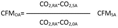
using the supply air volumetric flow rate in CFM (or m3/sec) and the CO2 concentrations in ppm (parts per million).
4. The expression CO2,RA-CO2,SA / CO2,RA-CO2,OA can be viewed as a “flow coefficient” that determines the “outdoor air fraction” in the supply air. The typical return air CO2 concentration in an occupied building is in the range of 500 to 1000 ppm while the outdoor air CO2 concentration is in the range of 350 to 450 ppm. The mixing of the outdoor and return air streams will always cause the supply air CO2 concentration to be higher than that of the outdoor air and lower than that of the return air. When the outdoor and exhaust air dampers are fully closed and all the return air is being recirculated, the supply air CO2 concentration is equal to that of the return air and the flow coefficient will have a value of zero, correctly indicating that no outdoor air is being introduced into the space. When the outdoor and exhaust air dampers are fully open, the supply air CO2 concentration is equal to that of the outdoor air and the flow coefficient will have value of one, indicating that the air handling unit is using 100% outdoor air.
5. Single CO2 sensor with a sampling air pump and appropriate software is used to measure and store, in sequence, CO2 concentrations of the three air streams. Two solenoid air valves are used to connect the appropriate sampling line to the air sampling pump and to the sensor. Adequate time is provided for purging each sampling line and for the time response of the CO2 sensor.
6. With the use of a single CO2 sensor, the relative differences between CO2 concentrations can be measured with an error of less than 5 ppm. The effect of sensing errors such as drift, temperature effect and short term output variations will be identical for all three CO2 measurements. Because the flow coefficient requires only calculation of the ratio of the CO2 differentials, the identical errors in the individual measurements will cancel out. Only infrequent field calibration of the CO2 sensor is required because only the differentials are used, rather than absolute values.
7. The return air CO2 concentration, one of the three CO2 concentrations read and stored during the multiplexing cycle, can be utilized in some cases for purposes other than indirect outdoor air flow calculation. For example, it can be used for CO2 high limit control and for Return Air CO2 Alarms. For these applications, when an absolute CO2 measurement is needed, accurate CO2 sensor calibration is required.
E. CO2 Sensing Point Location:
1. Selection of the CO2 sensing locations should be as follows. The sampling tube (typically a 1/4 inch diameter plastic tube) is inserted into the duct in any convenient and easily accessible section of the ductwork. Note that, contrary to temperature sensing, the CO2 concentration in mixed air is identical to the CO2 concentration in the supply air. Therefore, there is never any need to sense CO2 in the mixed air plenum where an averaging sensing probe would be required. Because the CO2 concentration of an air stream is not affected by heating coils, cooling coils or humidifiers, the sensing point for the supply can be located downstream of the supply fan to ensure that the outdoor and return air streams are well mixed and have minimum stratification. The return air sensing point can be located in the return air duct, upstream or downstream of the return fan.
2. The supply air sensing point is subject to the fastest changes in CO2 concentration, as the linked dampers change position. When presented with choices regarding equipment location, mount the controller in a location that will minimize the length of the supply air sensing tube, using a tube of up to 30 feet, in length.
3. The outdoor air sensing point should be located in free air outside the building or, alternatively, in the outdoor air intake. If the outdoor air CO2 sample is obtained from a location that is isolated from the building exhausts, the CO2 Concentration Balance method will automatically compensate for air which short-cycles from the exhaust louvers to the outdoor air intake. Either location compensates for air which short-cycles from the fan room into the mixing plenum. By placing the outdoor air CO2 sensing point in a location that is isolated from the building exhausts, this method allows calculation of the true fresh air portion of the outdoor air flow intake from the three CO2 measurements and the supply air flow. The outdoor CO2 sensing point, if placed in the outdoor air intake duct for convenience reasons, should be placed far enough on the upstream side of the outdoor air damper so that its reading is not affected by a possible “backwash” of the mixed air at larger outdoor air damper openings. A good practical test is to check the outdoor air CO2 sensing point reading while positioning the outdoor air damper from its fully closed to its fully open position and verify that the sensor reading does not change.