15.5 Pre-Conditioned Air and 400 Hertz Systems
An airline (tenant) assigned gates on a preferential use basis will be responsible for the installation and maintenance of PC and 400 Hz equipment on its preferential use passenger boarding bridges. Upon terminating the preferential use of the gate, the airline shall remove, at its sole expense, the PC Air and 400 Hz equipment.
MDOT MAA, which owns and assigns the common use gates, will be NOT responsible for the installation and maintenance of the PC Air and 400 Hz equipment on the common use passenger boarding bridge(s). MDOT MAA will determine the need and timetable for providing this equipment.
15.5.1 Design and Construction Requirements
A. Loading Bridge Requirements: Loading Bridges shall be specified to readily accept PC Air and 400 Hz equipment. In circumstances where the PC Air and 400 Hz equipment is to be installed at a later date, the loading bridge shall be specified to allow installation of the heaviest Point of Use (POU) equipment which satisfies the largest aircraft requirements of that gate.
B. All PC Air and 400 Hz equipment for preferential use and common use gates shall be designed and constructed to include separate metering, allow separate billing of electrical usage, and connection to MDOT MAA’s METASYS Building Management System.
C. All PC Air and 400 Hz equipment installed at existing gates and passenger boarding bridges shall be POU units.
D. All PC Air and 400 Hz equipment installed at newly constructed terminals and concourses shall be POU units. Centralized systems will be considered by MDOT MAA when the installer can meet the following requirements:
1. Demonstrates through cost benefit analysis the viability of the central system.
2. Agrees to lease all areas associated with the central system equipment.
3. Satisfies all concerns related to location of equipment in the building and on the aircraft ramp, line-of-sight issues, aesthetic issues, real estate issues, and operational issues.
4. For centralized PC Air, the glycol loop piping shall be constructed with soldered or welded joints (not threaded), and will be placed in the lower level only, keeping it out of public spaces. All main supply piping for the glycol loop shall be located in the interior of the building.
5. For 400 Hz systems, all main supply conduits and wires shall be located in the interior of the building, except for branch conduit and wire needed for connection to the passenger boarding bridge. 400 Hz systems are known to produce harmonics. In order to mitigate the harmonic effects, each piece of 400 Hz equipment must comply with the following performance criteria:
E. All PC Air and 400 Hz units shall be located on the underside of the passenger boarding bridges when possible. In situations where the PC Air unit prohibits the PBB from lowering to the required height to mate to an RJ Aircraft, the unit may be required to be installed on top of the PBB. No ground mounted units are permitted.
1. Harmonics content: total harmonic distortion of the input current wave form, as measured at the input terminals, shall be 30% of the lower whenever load is 50% of rated output or higher.
2. Power factor: the power factor measured at the input terminals shall be 90% or higher whenever load is 50% of rated output or higher.
F. Minimum height restrictor brackets shall be placed on all vertical lift columns to protect bridge-mounted equipment
G. Installation of the PC Air and 400 Hz equipment on the passenger boarding bridge should not affect the structural integrity, operation, or the warranty of the passenger boarding bridge.
H. Building Permit Approval: An airline (tenant) installing PC Air and 400 Hz equipment at its preferential use gate(s) will be required to obtain an MDOT MAA building permit. Notwithstanding the other requirements of the building permit process, the airline will be required to coordinate the installation of PC Air and 400 Hz equipment with MDOT MAA’s passenger boarding bridge repair and maintenance contractor. MDOT MAA’s contractor will review and inspect the installation. In addition, catalog cuts and data for all proposed equipment should be submitted to MDOT MAA for review and approval.
This standard is intended to require metering for all PBB electrical power for bridge power 400 Hertz, ground power and Pre-conditioned Air.
Electrical power is used at boarding bridges in three ways:
1. To position bridges up to aircraft doors and maintain bridges at an elevation matching the door height while the aircraft is parked at the gate (Bridge Power).
2. To provide ground power to operate electrically powered aircraft equipment, which uses power at 115 volts, alternating 400 times per second (400 Hertz), or in some cases at 28 volts Direct Current (DC).
3. To provide heated or cooled air to aircraft, called “Pre-conditioned Air” or PC Air (PCA).
15.5.2.1 Metering on Existing Passenger Boarding Bridges
Electrical metering is on all existing PBBs. During the design phase, the Consultant shall verify electrical metering is present for existing gates.
Existing loading bridges at BWI Marshall are outfitted with Bridge Power and various combinations of 400 Hertz and PCA units, powered in varying ways as outlined below:
A. Gates at Terminal A/B have a common circuit for Bridge Power and PCA at each gate. 400 Hertz is provided from a centralized system utilizing two motor generator sets.
B. Some bridges on Piers C, D, and the International Terminal have bridge-mounted 400 Hertz units, so called “Point of Use” or POU units. Some bridges are equipped with PCA units.
C. The existing bridge-mounted installations include the following arrangements:
1. Bridge Power only, no PCA or 400 Hertz
2. Same circuit for Bridge Power, PCA and bridge-mounted 400 Hertz (POU)
3. Same circuit for Bridge Power and PCA (or 400 Hertz)
4. Individual circuits for Bridge Power, PCA and/or 400 Hertz
15.5.2.2 Requirements for Providing Metering on Existing Passenger Boarding Bridges
Provision of 400 Hertz and Pre-Conditioned Air at loading bridges that do not currently have them shall be a shared responsibility between MDOT MAA and the tenant. The tenant shall be responsible for providing the equipment as necessary, installing panels, wiring, and conduits, disconnect switches, and related equipment to provide the electrical infrastructure necessary to support the improvements.
The tenant shall obtain a building permit for the proposed improvements. The MDOT MAA shall be responsible for providing metering of the additional electrical service and modifications to the accounting system necessary to reflect the proposed service. Coordination of the timing of the improvements shall be the responsibility of the tenant.
The airport currently has a centralized metering data collection system. The meters required will be tied into the existing system, so that the Maryland Aviation Administration can charge these tenants to recover costs incurred by the airport for providing electrical power.
15.5.2.3 Metering Requirements for New or Renovated Passenger Boarding Bridges
Electrical metering shall be added to new gates. Coordinate with the MDOT MAA Project Manager during design.
A. New or renovated loading bridges shall have individually metered circuits for:
1. Bridge Power
2. PCA (if equipped on bridge)
3. 400 Hertz (if equipped on bridge, whether POU or Centralized)
B. The meter for each circuit shall be one of the following listed below and be fully compatible with the existing Square-D TMSCE (Tenant Metering Software Commercial Edition), Version 2.5 or higher and the System Management Software (SMS).
1. High Density Metering (HDM) enclosure with PM750 meters (one meter per circuit). Provide 120V control power to HDM enclosures as necessary.
2. Enhanced Enercept Meter, rated for circuit.
C. Daisy chain requirements:
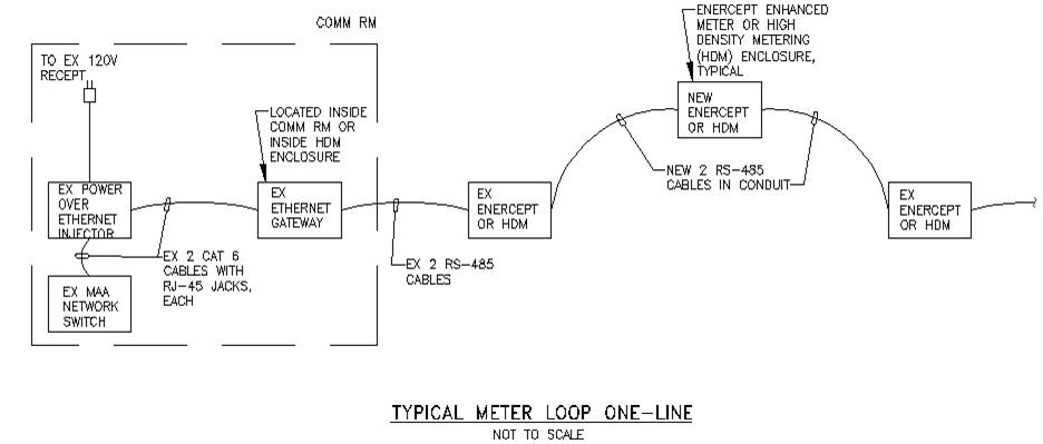
1. Daisy-chain connect each Enhanced Enercept meter to the existing metering network using two RS-485 cables (1 cable as spare) in 1” conduit. RS-485 cable shall be 600V rated Belden 1120A, or approved equal. Refer to the one-line diagram, “Typical Meter Loop One-Line.”
2. Daisy-chain connect the HDM enclosure to the existing metering network using two plenum-rated RS-485 cables (1 cable as spare). RS-485 cable shall be 300V rated Belden 82841 cable, or approved equal.
3. Each RS-485 daisy-chain network shall provide maximum 32 devices at cable length of maximum 4000 feet.
D. Provide testing and verifications procedure to ensure functionality of meters.
E. The existing TMSCE and SMS software shall be updated to reflect the new work.