8.5 Terminal Building Head Knockers
Terminal building head knocker structures shall be provided at each end of each at-grade through traffic vehicle passageway (tunnel) that traverses beneath an elevated portion of the terminal building. The free-standing head knockers shall protect the face of the building by preventing oversized vehicles from passing and making contact with the at the tunnel entrance.
8.5.1 Head Knocker Location
Head knockers shall be located at each end of each through vehicle passageway to protect the overhead portion of the building above the passageway. The head knockers shall clear span the full width of the passage and neither the head knocker frame nor any of its components or supports shall impede vehicle travel below the posted clear height or within the full width of the travel lanes.
The centerline of head knocker structures shall be located a minimum of 5’-0” from the face of the building and shall not be positioned any further from the face of the building then would allow passage of vehicles between the head knocker and the building. If conditions, such as adjacent existing building elements or equipment, require the head knocker to be closer to the building than 5’-0”, coordinate location with BWI Airport Operations and verify clearances with existing building foundations.
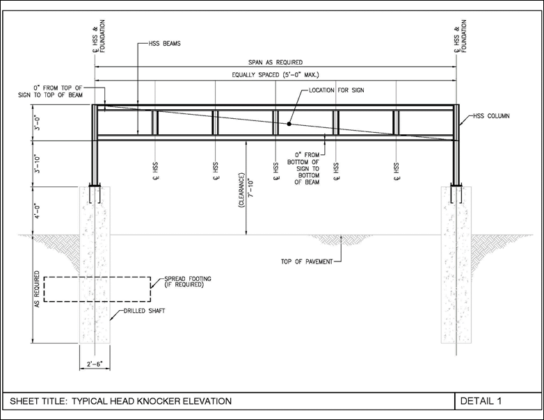
Head knockers shall provide 7’-10” clearance. If a lower clearance is required to protect building elements, coordinate with BWI Airport Operations for approval.
Head knockers must be positioned clear of existing and anticipated airfield and building infrastructure elements, such as sidewalks, below grade-utilities and high-mast light poles. Clearance must be maintained around high-mast light poles for lowering of the fixtures for maintenance. Head knockers must not reduce the width of Vehicle Service Road (VSR) lanes or other vehicle pathways.
Head knocker locations shall not impede fire truck access, including roof access, or access to or from egress doors or walkways. Head knocker supports shall not be positioned within in the path of sidewalks or protection curbs, unless there is no other acceptable location, and only with the approval of the BWI Fire Marshal. Head knockers shall not impede, block or otherwise obstruct any fire suppression systems to include, but not limited to, fire hydrants (free standing or wall hydrants), fire department automatic sprinkler or sprinkler/standpipe connections, fire pump connections or test headers, and should not impact established fire lane markings as required in the Annotated Code of Maryland, Title 21, Subtitle 10, Section 21-1003(m) as well as stipulated in NFPA 1, Fire Code, Chapter 18.
Final location of head knockers must be approved by the BWI Fire Marshal.
8.5.2 Head Knocker Civil Design Requirements
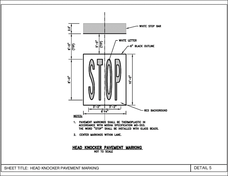
Head knockers shall be installed to clear span existing drive aisles. Existing lane pavement markings shall remain. A painted STOP line marking, including a painted stop bar shall be installed in the direction of travel in each lane at each head knocker.
Field investigation of existing utilities, either as part of the design or mandated for the contractor, shall be performed to aid in locating the head knockers clear of existing foundations and to prevent damaging utilities during construction.
Pavement repairs shall be included for the areas at the head knocker foundations and for trenching required for installation of electrical conduits.
8.5.3 Head Knocker Structural System
Head knockers shall be designed to resist a horizontal 10,000 pound concentrated load applied at any location along the length of the head knocker frame. The frame shall also resist other code applicable structural loads.
The head knocker structure shall be a welded steel frame composed of hollow structural sections. A top and bottom horizontal section of equal size shall be provided to support attached signage and resist applied loads. Intermediate, equally spaced vertical hollow structural sections shall also be provided to connect the top and bottom sections and provide signage support. Spacing of the intermediate sections shall not exceed 5’-0”. The base of the steel frame shall be elevated above grade a minimum of 4’-0” on concrete pedestals. The reinforced concrete pedestals shall be 2’-6” in diameter.
Foundations shall be provided to resist the applied and self-weight loads on the frame, signage and attachments. Foundation placement must be clear of existing foundations and utilities. Foundations shall be reinforced concrete drilled piers, or reinforced concrete spread footings if below grade obstructions make drilled piers impractical. Offset foundations to accommodate head knocker placement must be structurally adequate. Foundation design soil and subgrade parameters are site specific and shall be determined by the consultant.
The steel frame shall have a multi-coat, high-performance epoxy coating. Color shall be Safety Yellow.
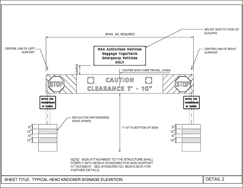
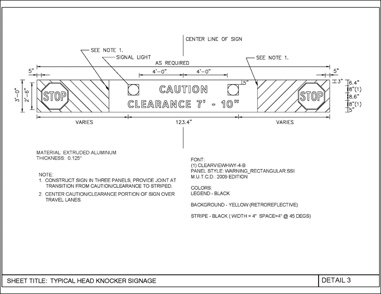
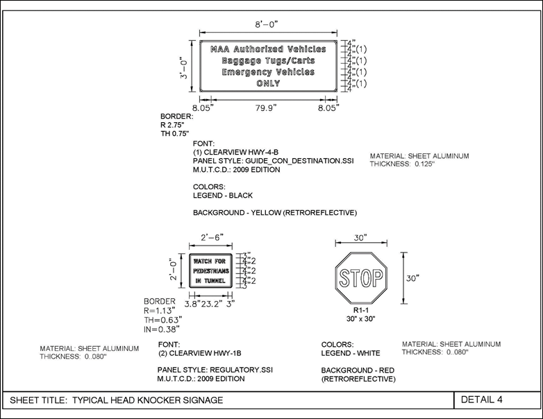
8.5.4 Head Knocker Signage
The head knocker frame shall include Caution, Clearance and Stop signs mounted over the clear drive aisle. Each head knocker shall include Pedestrian Warning signs attached to the vertical columns, reflective stripes on the concrete pedestals and an MDOT MAA User Authorization sign mounted to the face of the building. The Caution/Clearance/Stop sign shall accommodate surface mounting of signal lights. Signage lettering and colors are as indicated. Signs shall be fabricated from sheet aluminum, with joints as indicated and mounted to the head knocker frame with banding strap and universal channel clamps attached to sign with rivets. Do not screw the signage directly to the head knocker frame. Wall mounted signage shall be screwed directly to the metal panel or masonry exterior wall of the building.
Signage shall be governed by the standards and requirements of the current versions of the following publications:
FHWA “Manual on Uniform Traffic Control Devices” (M.U.T.C.D.)
MDSHA “Maryland Manual on Uniform Traffic Control Devices” (MdMUTCD)
AASHTO “Highway Safety Design and Operations Guide”
AASHTO “Standard Specifications for Structural Supports for Highway Signs, Luminaires and Traffic Signals”
(Category II for all Overhead and Cantilever Sign Structures)
The disposition of existing signage shall be coordinated with BWI Airport Operations.
8.5.5 Head Knocker Electrical Requirements
Each head knocker shall be equipped with two 120V red LED flashing 12-inch diameter signal light fixtures with glass lens and aluminum enclosures. The fixtures shall be surface mounted to the signage. Power for the lights shall be provided from the existing signal light circuit or from a nearby panel as required. Wiring shall be copper. All exterior conduits (exposed and underground) shall be rigid galvanized steel and a minimum of 1-inch. Junction boxes shall be cast metal weatherproof type FS. Conduit from the sign frame to the face of the terminal building shall be installed below grade. Do not mount conduit overhead. Conduit shall be surface mounted to the head knocker frame and embedded within the concrete pedestal.
Each head knocker frame shall be grounded with a #8 bare copper conductor and ¾” x 10ft. copper ground rod.
8.5.6 Head Knocker Exhibits and Standard Details
The following pages include standard head knocker elevations and signage details to be utilized for head knocker designs.