11.2 Grounding and Lightning Protection
11.2.1 Grounding
Whenever grounding electrode conductors are bonded to ground rods or other grounding electrodes, bonds shall be exothermic welds. Exothermic welds shall be coated against corrosion where direct buried.
Ground Rods: Ground Rods shall be ¾” in diameter, 10’ long as a minimum. Materials of construction shall be copper-coated steel as a minimum. Ground rods shall be designed and installed per the National Electric Code.
11.2.2 Surge Suppression, Bonding and Grounding for Outdoor Systems
Surge Suppression, Bonding and Grounding, shall be included in the specifications and plans for the following outdoor installations:
1. Parking and Revenue Control Systems
2. Closed Circuit Television System (CCTV) Installations
3. Access Control
4. Any unprotected system that may be struck by lightning that would conduct the lightning energy to the inside of the facilities.
Note: Equipment product catalog numbers included in this design standard are for equipment manufactured and provided by Emerson Network Power, EDCO, Transient Voltage Surge Suppression, or by General Electric but these are not meant to be sole source or proprietary specifications. Products by other manufacturers, which meet or exceed the specifications of the named products and include salient features matching those named may be specified, and used.
11.2.2.1 Protection for Parking and Revenue Control Systems
Surge suppression devices shall be installed on all electrical conductors connected to lane toll equipment (revenue plaza equipment, ticket dispensers (spitters) and gates). Typical installations include data cabling (RS-422 for example) and electrical power circuits that feed the lane equipment, and booths.
A. Protection for Data Cabling
The RS 485/RS-422 circuits shall be protected with an EDCO PC-642-008LC signal line protection device. This device provides two stages of protection with an 8-volt clamp which coordinates well with the 6-volt normal operating voltages on RS-422/485 circuits. The LC suffix indicates low capacitance which allows the suppressor to operate at higher data rates. The EDCO PC series suppressor modules shall be ordered with a model PC-BIB base assembly. The first stage (odd numbered) terminals shall be connected to the field-side wiring and that the second stage (even numbered) terminals shall be connected to the equipment-side cabling to the protected equipment.
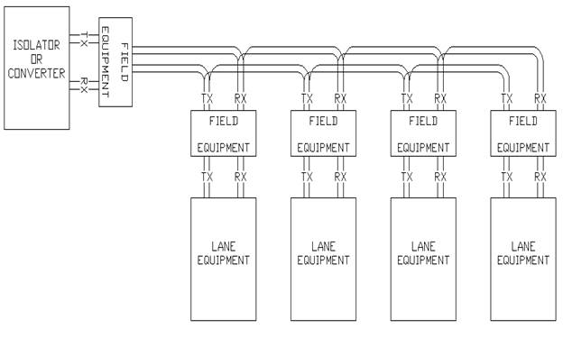
Many locations run RS-422 cables from lane-to-lane in a daisy-chain fashion (parallel connections). In these locations the inter-lane cabling shall be bridged in and then out to the next lane on the field-side wiring of the suppressor. This requires separate inbound and outbound inter-lane cables connected to the field-side of the suppressor with a short pigtail data cable between the suppressor equipment-side and the lane equipment. A suppressor shall be installed on the end of the inter-lane cabling where it attaches to an isolator or protocol converter. Figure 1 below shows the inter-lane cabling configuration graphically.
Figure 1 – Inter-Lane Cabling Configuration
Power ground wires and signal suppressor ground wires shall be as short as possible and be bonded to the equipment chassis as physically close to the suppressor as possible. This will minimize the effects of inductive voltage drop across these conductors and help control the voltage excursions that occur during a surge between the protected conductors and the equipment chassis. Figure 2 below from the EDCO suppressor’s application notes depicts these details.
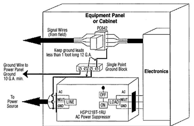
Figure 2 – Chassis Bonds for Suppressor Grounds
B. Protection for 120 Volt AC Powered Equipment
The 120 Vac powered cashier interface terminals, ticket spitters and gates shall be protected with either an EDCO model HSP121BT or a model HSP121A surge suppressor.
The EDCO HSP121BT has an external barrier strip which is suitable for installation inside ticket spitters, and gate operator housings that are not normally accessible to the cashier or others.
The EDCO HSP121A is mounted in a NEMA enclosure and has an internal terminal strip and knockouts that will accept conduit fittings or cord strain relief fittings. The EDCO HSP121A shall be used inside the cashier booths for protection of the cashiers’ interface terminals. Using a cord strain relief fitting, the device shall be hard wired in series with the power input to the UPS at the booths. This will help ensure that the cashiers do not plug heaters into an unused receptacle protected by the surge suppression device as these devices are only rated for 15 amperes.
At the gates, these units shall be used to protect the 120 Vac feed to the controllers with the 120 Vac for the motors taken off upstream of the device. Motor loads shall not be fed through the surge suppressors.
The central equipment is typically located at the equipment cabinet in the Toll Plaza Administration building. The power equipment in the closet cabinet is usually supported by one or two plug-strips. An EDCO TS-1200G suppressor which will plug into one of the receptacles located in the cabinet shall be used. The plug-strip(s) can then be plugged directly into the EDCO TS-1200G. The “G” in the part number is an external binding post ground terminal. It connects to the internal grounds in the suppressor and provides a good point to attach the ground leads from the data line suppressors.
11.2.2.2 Protection for Closed Circuit Television Systems
Remote Closed Circuit Television (CCTV) cameras located at gates and parking areas are particularly susceptible to damage from lightning, largely due to the high level of exposure to direct lightning strikes or strikes in near proximity.
Protection for CCTV Cameras
The CCTV cameras typically include pan tilt assemblies, and are integrated units requiring 24 Vac power, RS-485 4-wire pan-tilt-zoom control and a coaxial video connection. A NEMA 4X rated equipment enclosure is typically installed at the base of each tower. This enclosure contains a quad electrical receptacle, a fiber-optic transceiver for video and control, a power transformer for camera power and a separate power transformer for the fiber-optic transceiver. Adequate space must be provided in the enclosure for the required surge suppression devices.
Figure 3 below depicts several measures that shall be taken at typical tower locations. An air terminal, fashioned from a galvanized ground rod shall be installed to protect the camera housing from direct lightning strike currents. A ground rod and bonding conductor to the tower shall be added to improve the ground resistance of the tower foundation. Continuous steel conduit shall be installed from the camera housing to the equipment enclosure to help shield the camera cabling from induced voltage if the tower is struck by lightning.
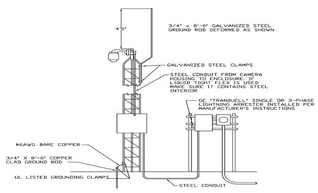
Figure 3 – CCTV Camera Tower Recommendations
Because of the relatively high exposure of these sites a high energy Metal Oxide Varistor (MOV) arrester shall be installed at the electrical panel serving each camera tower. The product recommended is a General Electric Tranquell device in either a 120/240 Vac single phase or 120/208 Vac three phase configuration. These units install in a knockout in the panel and either is directly connected to the buses or connected through a 30-ampere breaker. These units are rated for 10,000 ampere Category C exposure conditions and they will provide a first stage clamp down to a level between 2 kV and 3 kV. This provides an additional level of protection that will help extend the lifespan of suppressors installed inside the camera cabinet.
Figure 4 below shows the recommended configuration for the CCTV power, video and RS-422 pan-tilt-zoom control circuits at the base of the tower. These enclosures are typically equipped with quad 120 Vac receptacles to plug-in the camera power transformer and the plug-in DC supply for the fiber transceiver. Protect these receptacles with an EDCO HSP-121A, NEMA 4X, 120 Vac, suppressor. This suppressor (shown as A on Figure 4) is shown interconnecting these receptacles with the incoming power conductors. This suppressor will control voltage excursions from line-to-neutral and from line-to-ground to about 300-400 volts during 10 kiloampere Category C surge conditions. These suppressors are required in these locations due to the high exposure levels to direct lightning.
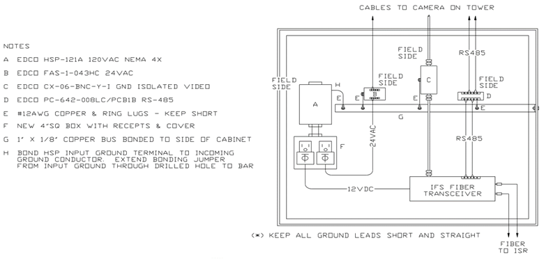
Figure 4 – CCTV Equipment Enclosure Recommended Configuration
An EDCO FAS-1-043HC, two-stage, suppression shall be installed to protect the 24 Vac power conductors to the camera assembly. This suppressor uses series inductors between the first and second stage rather than resistors, allowing it to pass several amperes of current.
An EDCO CX-06-BNC-Y-I, coaxial suppressor (shown as B on Figure 4) shall be installed to protect the camera video cable. This suppressor uses a female BNC connector on both the field-side and equipment-side. A clamp voltage of 6‑volts is recommended as the peak-to-peak video levels should be around one volt.
An EDCO PC-642-008LC/PCB1B, two-pair low capacitance suppressor (shown as D on Figure 4) shall be installed to protect the RS-485 circuits with a clamping voltage of eight volts. This is consistent with the 6‑volt operating range for the suppressor. This suppressor is polarity insensitive. The part number for this unit also includes a plug-in screw terminal base.
A copper ground bus (shown as G on Figure 4) shall be installed to terminate the ground leads for the suppressors. A flat conductor provides a significantly lower inductance than a round conductor, which is a major factor in having the suppressors track each other during high levels of lightning current. The bus bar is shown bonding to the side of the cabinet with stainless steel hardware and star washers to ensure that potentials inside the enclosure remain consistent with each other.
The power suppressor has a terminal strip for line, neutral and ground on both the unprotected and protected side. Line, neutral and ground conductors shall terminate on these strips. In addition, a #12 AWG copper conductor is shown between the unprotected ground terminal and the copper bus for the cabinet. This will help to ensure that the ground reference for the power suppressor and ground leads for the other suppressors track each other during surge handling.
Properly connect the suppressors with their unprotected or field-side wiring terminals to the cabling leaving the enclosure. If connected backwards, the more sensitive (but faster acting) second stage will be exposed to excessive current and the suppressors may be damaged by the first lightning event.
Separation of cabling is required to minimize coupling between protected and unprotected cabling. If it is necessary to cross these cables over each other, make the crossover using right angles. This will help to minimize the inductive and capacitive coupling of energy between protected and unprotected circuits.
Protection is not provided for the 12 Vdc power supply to the IFS transceiver as this power circuit does not leave the enclosure.
11.2.2.3 Protection for Access Control System Gates
Due to the exposed location of access control components located at vehicular gates, there is likely to be damage by direct or nearby lightning strikes and the metallic fencing’s ability to conduct nearby strikes to the gate locations.
Figure 5 shows the recommended method for protecting the access control equipment at the gates. Install an EDCO HSP-121A, two-stage hybrid, NEMA 4X, suppressor (See A on Figure 5) on the exterior of the access control enclosure to protect the power conductors. This approach is recommended as access control enclosures typically have insufficient space to place the suppressor in the housing. The incoming 120 Vac power entering the enclosure is looped out, through the suppressor and back into the enclosure where it is hard-wired to the 27 Vdc regulated switching power supply.
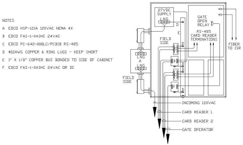
Figure 5 – Gate Access Control Recommended Configuration
An EDCO FAS-1-043HC, two-circuit, 24 Vac, suppressor shall be installed at each gate to protect the wiring to the two card readers. This EDCO AC suppressor was chosen for this application as the 27 Vdc used to power the remote readers is on the upper limit of what a 24 Vdc suppressor will tolerate. Since peak voltage on an AC circuit is 1.41 times the RMS value, the clamping threshold for the AC suppressor is actually set at 43-Volts. The suppressors for card reader power utilize a series inter-stage inductor rather than resistors making them suitable for this type of powering application.
Use EDCO PC-642-008LC/PCB1B, low capacitance, 8-volt, RS-485, suppressors for protection of the card reader data circuits. These suppressors shall include a plug-in screw terminal base that can be secured to the back or side panels in an enclosure.
In the event that Wiegand readers are ever required, the same manufacturer makes a 5-conductor Wiegand protector in the same package.
In lower exposure areas, there would not be concern about circuits that leave the enclosure isolated by a dry relay contact. Cases of welded relay contacts, contacts burned open and even miniature relays which were completely disintegrated have occurred in high exposure level situations. When this occurs there is often collateral damage to other components on the circuit board.
A 24 Vac suppressor shall be specified for in high exposure level situations. This is usable with AC or DC control voltages of up to about 30 volts as the clamping threshold is set at 43 volts. If higher voltages are required, a different suppressor may be utilized with a clamp setting that is workable with the voltage being switched.
All of the rules and guidelines recommended for the CCTV enclosure apply to the card access installation. This includes separation of protected and unprotected conductors and keeping ground leads short.
No detail was produced for the remote card readers themselves. These readers shall be equipped with one of the reader power suppressors (also available in a single pair configuration) and an RS-485 suppressor installed in the junction box behind the reader. Bond suppressor grounds to the metallic housing for the reader and reader pedestal.