2.3 Bird Deterrent Systems
2.3.1 Waterfowl Deterrent System for Sediment Traps at BWI Marshall
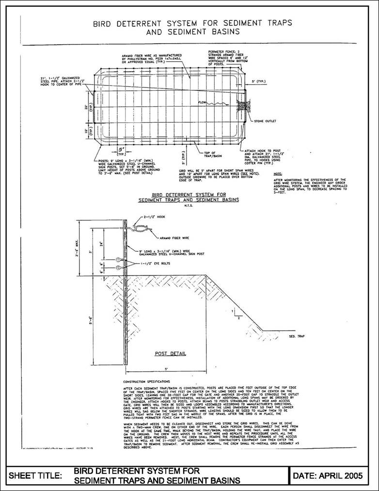
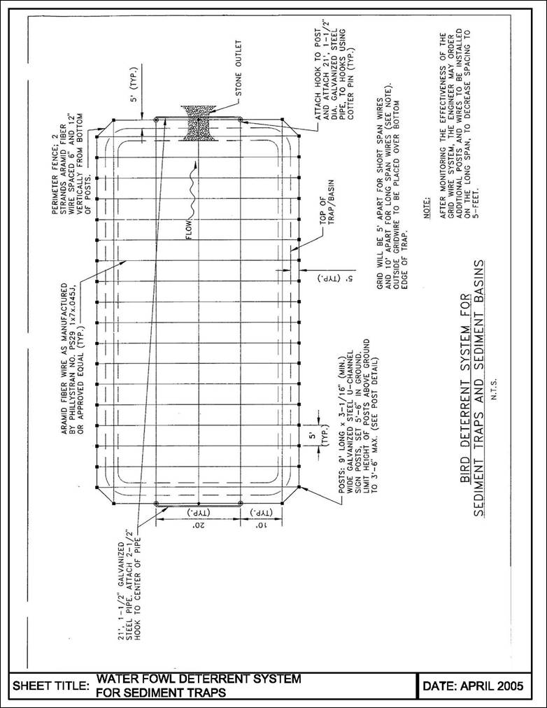
There is a need to discourage ducks and other waterfowl from being attracted to stormwater in sediment traps. The system proposed for BWI Marshall will interfere with the ducks’ landing pattern by installing a grid using lightweight wire above the surface of the trap. As they approach a water-filled trap, ducks, geese, and other waterfowl will see the grid wires and not attempt to land. A perimeter fence consisting of two wire strands strung around the posts will keep birds from walking onto the traps.
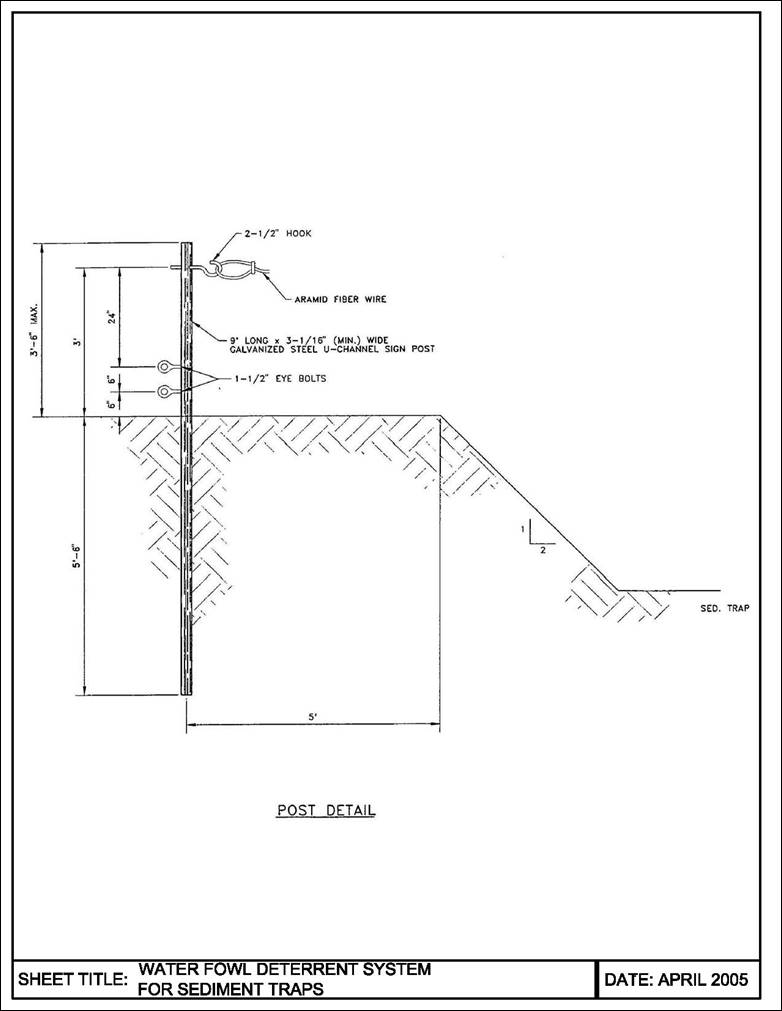
Initial grid spacing will be five feet for short spans and ten feet for long spans. See details for a typical layout. The ends of the grid wires will be strung from hooks placed on posts three feet above the ground. It is expected that the wires will sag as much as two feet and will exert a maximum line tension of thirty-five pounds.
Grid wire will be high-strength, lightweight synthetic material made from aramid fiber as manufactured by Phillystran, Inc., Part No. PS29 1x7x.045J, or approved equal.
Posts will be nine-foot long galvanized steel U-channel signposts, driven five and one half feet into the ground. The height above ground shall be no more than three and one half feet. Three holes will be drilled into each post to attach one 2 ½ inch hook and two 1 ½ inch eye bolts.
An access gate will be installed on the short end opposite the outlet to facilitate trap cleanout. Each gate consists of a twenty foot long, 1 ½” diameter horizontal pipe placed three feet above ground and spanning two posts spaced twenty feet apart. When sediment is to be cleaned out from the trap, the long pipe is removed. An identical horizontal pipe will also span the stone outlet weir at the opposite end of the trap. Each pipe will have a hook placed in the middle to attach the grid wire.
|
Sediment Trap Bottom Dimensions, ft. |
Approximate length per Gridwire, ft. |
Number of Gridwires |
Total length of Gridwire ft. |
Total length of Perimeter Fence ft. |
Number of Posts |
|
40’ x 85’ |
113’ |
5 |
565’ |
362’ |
44 |
|
68’ |
18 |
1,224’ |
|||
|
Trap TOTAL: |
1,789’ |
||||
|
40’ x 70’ |
98’ |
5 |
490’ |
332’ |
38
|
|
68’ |
15 |
1,020’ |
|||
|
Trap TOTAL: |
1,510’ |
||||
|
30’ x 105’ (2 traps) |
125’ |
4 |
500’ |
350’ |
50
|
|
50’ |
22 |
1,100’ |
|||
|
Trap TOTAL: |
1,600’ |
||||
|
30’ x 150’ |
175’ |
4 |
700’ |
450’ |
70 |
|
50’ |
32 |
1,600’ |
|||
|
Trap TOTAL: |
2,300’ |
||||
|
30’ x 155’ |
170’ |
4 |
680’ |
440’ |
68 |
|
50’ |
31 |
1,550’ |
|||
|
Trap TOTAL: |
2,230’ |
||||
|
GRAND TOTAL: |
11,029’ |
2,284’ |
320 |
||
2.3.2 Procedure for Installing and Removing Grid Wire System
After each sediment trap is constructed, posts are placed five feet outside of the top edge of the traps, spaced five feet on center on the long side of the trap and ten feet on center on the short sides, leaving one twenty foot gap for the gate. Attach hooks to posts. Attach beams to posts straddling outlet weir and access gate. Grid wires will then be sized and loops assembled according to manufacturer’s directions. Grid wires are then attached to posts starting with the long dimension first so that the longer wires will sag below the shorter strands. Wire lengths should be sized to allow them to be pulled tight with two feet sag in the middle of the spans. After the grid is in place, the two-strand perimeter fence can be installed.
When sediment needs to be cleaned out, disconnect, and store the grid wires. This can be done with a two-man crew, one on either end of the wire. Each person shall disconnect the wire from the hook at the same time, walk beyond the trap, holding the wire taut, and place the wire on the ground. The crew then moves to the next wire and repeats the procedure until all the wires have been removed. Next, the crew shall remove the perimeter fence strands at the access gates as well as the twenty-one foot long horizontal beam. Contractor’s equipment can then enter the trap to remove sediment. After sediment removal, the crew shall re-install grid assembly as described above.