3.3 General
3.3.1 Drawing Definitions
The following sections define general A/E/C drawing types.
3.3.1.1 Engineering Drawings
Engineering drawings are formal representations used to convey the physical and functional end product design and/or installation requirements of an item. They may include pictorial, graphical, schematic or textual presentations.
3.3.1.2 Construction Drawings
Construction drawings are engineering drawings, which show the design of buildings, structures, or the related construction, and are normally associated with the architectural, construction and civil engineering operations. Construction drawings establish all the interrelated elements of the pertinent services, equipment, utilities, and other engineering skills.
3.3.1.3 Installation Drawings
Installation drawings are engineering drawings, which show the installation requirements of equipment in facilities.
3.3.1.4 Space Allocation Drawings
Space allocation drawings are used to provide an accurate record of existing space, identify tenants and square footages of occupancy.
3.3.2 MDOT MAA AIRPortal PEGS Reference Documents Library
As a consultant performing services for MDOT MAA, it is assumed that individuals providing engineering services for MDOT MAA have an account to AIRPortal, MDOT MAA’s system of record. There are multiple applications and resources available through AIRPortal. One such resource is the PEGS Reference Documents library. Found in AIRPortal under General > PEGS Reference Documents, this library provides consultants and sub-consultants with access to the most current resources to prepare MDOT MAA-compliant products. Examples are:
Logos
Standard Borders
Standard Title Sheets
Layer Templates
3.3.3 Confined Space Drawings/Non-Confined Space/No-Entry Space Drawings
When a Civil or Subsurface Utility, Structural, Architectural, Mechanical, Plumbing, or Electrical Engineering project includes either an inspection of existing or design of new confined space (CS) structures, non-confined space (NC) with safety entry procedures structures, or no-entry space (NE) structures, data regarding each structure shall be included in the contract drawings and associated digital data submissions. Consultants shall submit confined space, , non-confined space and no-entry space CAD data at all design phases beginning with the 30% design phase (see PEGS V2, Chapter 3.2 Deliverables by Design Phase).
Before working with confined space data, consultants should be familiar with the MDOT MAA Confined Spaces guidelines in PEGS V7, Chapter 2 Confined Spaces, and the MDOT MAA GIS Standards in PEGS V1, Chapter 4 GIS Standards.
3.3.3.1 Submissions Format
Confined space, non-confined space with safety entry procedures structures, or no-entry space data in CAD shall be entered in a dedicated AutoCAD .DWG file, attached to plan sheets as an external reference (xref) as needed. Each CS, NC, and NE structure shall be represented by an AutoCAD block entity.
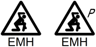
CS, NC, and NE block definitions, named spac-conf-prmt, spac-conf-nopr, spac-nent andspac-sfty-read, have been pre-defined by MDOT MAA, and contain attribute definitions which must be populated by the consultant. Spac-conf-prmt is to be used to represent unpermitted confined spaces, and spac-conf-prmt is to be used to represent permitted confined spaces. Spac-nent is to be used to represent no entry spaces and spac-sfty-read is to be used to represent non-confined spaces with safety entry procedures.
Figure 3.3.3.1a examples of spac-conf-nopr.dwg (non-permitted confined spaces) and spac-conf-prmt.dwg (permit required confined spaces)
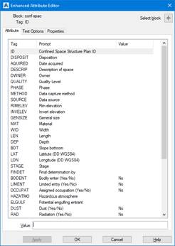
Figure 3.3.3.1b example of a spac-sfty-read.dwg (non-confined space with safety entry procedures)
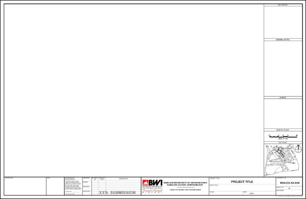
Figure 3.3.3.1c example of a spac-nent.dwg (no-entry spaces)
Click the following to download the AutoCAD DWG2013 files which may be inserted into any existing AutoCAD file to represent CS, NC and NE structures:
Spac-conf-nopr.dwg
Spac-conf-prmt.dwg
Spac-sfty-read.dwg
Spac-nent.dwg
3.3.3.2 AutoCAD Drawing Composition
Instances of the blocks spac-conf-prmt, spac-conf-nopr, spac-nent and spac-sfty-read should be inserted on the appropriate layer. Instances representing existing CS, NC, and NE structures may be inserted on layer C-CONF-EXST, C-NCONF-EXST, and N-NOEN-EXST, while those representing new work may be inserted on layer C-CONF-NEWW, C-NCONF-NEWW, and N-NOEN-NEWW.
The blocks spac-conf-prmt, spac-conf-nopr, spac-nent and spac-sfty-read are dynamic blocks with multiple visibility states, each corresponding to a type of CS, NC, and NE structure. After an instance of the block is inserted, the visibility state must be changed to indicate the type of structure it represents. By default, the block’s visibility state is set to EMH (electrical manhole).
The blocks also contain a set of AutoCAD Attributes, representing various types of data relating to CS structures. These attributes shall be populated by the consultant with all data known for each CS structure. See Section 3.3.3.4 Confined space attribute data for a list of these attributes.
3.3.3.3 Structure ID
Each CS, NC, and NE structure shall be given a unique Structure ID by the consultant. This Structure ID will be confirmed by MDOT-MAA following submission at the Conformed design phase.
CS Structure IDs shall for Civil and SUE projects shall consist shall consist of five parts, separated by underscores or dashes, as illustrated in Figure 3.3.3.3.
|
500’x500’ SUE Grid ID |
_ |
Structure Type Code |
_ |
X-Position |
- |
Y-Position |
_ |
Date of Installation (MMYYYY) |
Figure 3.3.3.3a, Structure ID Format for Civil/SUE
SUE Grid ID: The first part of the Structure ID shall be the Grid ID of the 500’x500’ SUE grid name in which the structure is located (See PEGS V1, Chapter 1.5 Subsurface Utility Engineering (SUE) Data Requirements for AIRPortal).
Structure Type Code: The second part of the Structure ID shall be the applicable Structure Type Code (see Table 33.3.3 below). The structure type codes coincide with SUE Aliases. NOTE: Consultants may request that MDOT-MAA create additional structure type codes, as needed.
X Position: The third part of the Structure ID shall be the distance perpendicular to the west edge of the SUE grid containing the structure, to the center of the structure (i.e. the X-coordinate within the SUE grid), rounded to the nearest foot; should a structure’s center fall directly on the boundary between two SUE grids, it shall be assumed to be located in the grid to the west at position 000
NOTE: Parts three and four are separated by a dash rather than an underscore
Y Position: The fourth part of the Structure ID shall be the distance perpendicular to the south edge of the SUE grid containing the structure, to the center of the structure (i.e. the Y-coordinate with the SUE grid), rounded to the nearest foot; should a structure’s center fall directly on the boundary between two grids, it shall be assumed to be located in the grid to the north, at position 000
Date of Installation: The fifth part of the Structure ID shall be the month and year of the structure’s installation in MMYYYY format; this part shall not be added until the Record or As-Built design phase, following the structure’s construction
Click here to download BWI_SUE_Grid.dwg, or here to download MTN_SUE_Grid.dwg, two AutoCAD DWG2013 files containing the SUE grids for both airports.
Example Structure ID’s:
38-35_TMH_152-156_012003 - SUE grid 38-35, Telecommunications Manhole, position 152ft east by 156ft north, installed January 2003
38-33_EMH_069-219_122003 - SUE grid 38-33, Electrical Manhole, position 069ft east by 219ft north, installed December 2003
36-31_SWI_385-385_011988 - SUE grid 36-31, Stormwater Inlet, position 385ft east by 385ft north, installed January 1988
CS, NC and NE Structure IDs for Structural, Architectural, Mechanical, Plumbing and Electrical projects shall consist of two parts, separated by an underscore or dash as illustrated in Figure 3.3.3.3b
|
Space ID |
_ |
Structure Type Code ID |
Figure 3.3.3.3b, Structure ID Format for Structural, Architectural, Mechanical, Plumbing and Electrical
|
Confined/Non-Confined/No Entry Space Structure Types and Codes |
|||
|
Structure Type |
Structure Type Code |
Location |
Space Type |
|
Electrical Manhole |
EMH |
Exterior/Interior |
Confined |
|
Telecommunications Manhole |
TMH |
||
|
Sanitary Sewer Manhole |
SSM |
Exterior |
|
|
Sanitary Sewer Lift Station/Ejector |
SSL |
||
|
Storm Water Manhole |
SWM |
||
|
Storm Water Lift Station |
SWL |
||
|
Storm Water Inlet |
SWI |
||
|
Water Booster Pump Station |
WPS |
||
|
Glycol Diversion Vault |
GDV |
||
|
Glycol Force Main Vault |
GFM |
||
|
Glycol Lift Station |
GLS |
||
|
Glycol Storage Tank |
GST |
||
|
Oil Water Separator |
OWS |
||
|
Hydrant Fuel Manhole |
HFM |
||
|
Ejector Sewer Pit |
ESP |
Interior |
Confined |
|
Plumbing Chase (w/ Access Panel) |
PC2 |
||
|
Air Intake Shaftway |
AIS |
Non-Confined |
|
|
Plumbing Chase (w/ Access Door) |
PC1 |
||
|
Utility Chase |
UCH |
||
|
Utility Shaftway |
USH |
||
|
Louver Intake Shaftway |
LIS |
||
|
Exhaust Air Louver |
EAL |
Confined |
|
|
Outdoor Air Intake |
OAI |
Non-Confined |
|
|
Heating and Ventilation Unit |
HVU |
||
|
Electrical Trench |
ELT |
||
|
Storm/Sanitary Drain Manhole |
SMH |
Confined |
|
|
Abandon Pit |
PIT |
||
|
Air Handling Unit |
AHU |
Non-Confined |
|
|
Supply Air Duct |
SAD |
||
|
Return Air Duct |
RAD |
Confined |
|
|
Fire Damper Access |
FDA |
No-Entry |
|
|
Outside Air Duct |
OAD |
Non-confined |
|
|
Interstitial Space |
ISS |
Confined |
|
Table 3.3.3.3, Confined/Non-Confined/No-Entry Space Structure Types and Codes
3.3.3.4 Confined/Non-Confined/No-Entry space attribute data
The blocks spac-conf-prmt, spac-conf-nopr, spac-nent and spac-sfty-read contain AutoCAD attribute definitions which must be populated for each CS, NC, and NE structure. There is no AutoCAD attribute definition for Structure Type, since this data is represented by the block’s visibility state.
The attribute definitions within the block are all set to be invisible, to avoid creating visual clutter in the plan set. However, attribute values may be viewed and edited at any time by double-clicking an instance of the block, which will open AutoCAD’s Enhanced Attribute Editor.
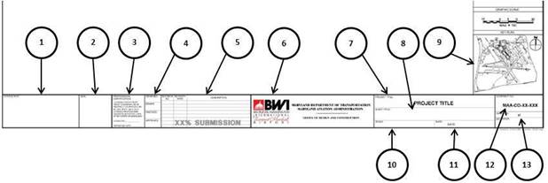
Figure 3.3.3.4 AutoCAD Enhanced Attribute Editor
|
Attributes defined in block spac-conf-prmt, spac-conf-nopr, spac-nent and spac-sfty-read |
||||
|
Category |
Attribute Name |
Attribute Tag |
Attribute Prompt |
Example Value |
|
GENERAL INFORMATION |
ID: |
ID |
Structure ID |
404-54-EMH-001 |
|
DISPOSITION: |
DISPOSIT |
Disposition |
IN SERVICE |
|
|
DATE ACQUIRED: |
ACQUIRED |
Date Acquired |
20190405 (formatted YYYYMMDD) |
|
|
DESCRIPTION OF SPACE: |
DESCIP |
Description of Space |
ELECTRICAL MANHOLE WEST OF EMPLOYEE PARKING LOT |
|
|
SPACE ID: |
SPACEID |
Room ID |
BT303A |
|
|
OWNER: |
OWNER |
Owner |
MAA |
|
|
QUALITY LEVEL: |
QUALITY |
Data quality level |
D |
|
|
PHASE: |
PHASE |
Phase |
CONFORMED |
|
|
CAPTURE METHOD: |
METHOD |
Data capture method |
CAD DIGITAL |
|
|
DATASOURCE: |
SOURCE |
Data source |
MAA-CO-19-006_C2.02 |
|
|
PHYSICAL PROPERTIES |
RIM ELEVATION: |
REMELEV |
Rim elevation |
110.55 |
|
INVERT ELEVATION: |
INVELEV |
Invert elevation |
108.08 |
|
|
GENERAL SIZE: |
GENSIZE |
General size |
4’-2” |
|
|
MATERIAL: |
MAT |
Material |
PRECAST |
|
|
WIDTH: |
WID |
Width |
5’-6” |
|
|
LENGTH: |
LEN |
Length |
3’-6” |
|
|
DEPTH: |
DEP |
Depth |
3’-0” |
|
|
SLOPE BOT: |
BOT |
Slope bottom |
999 |
|
|
LATITUDE (DD WGS84): |
LAT |
Latitude (DD WGS84): |
39.177579 |
|
|
LONGITUDE (DD WGS84): |
LON |
Longitude (DD WGS84): |
-76.668939 |
|
|
ASSESSMENT VALUES |
STAGE: |
STAGE |
Stage |
PERMIT REQUIRED CONFINED SPACE |
|
FINAL DETERMINATION BY: |
FINDET |
Final determination by |
JOHN SMITH |
|
|
BODILY ENTRY: |
BODENT |
Bodily entry (Yes/No) |
YES |
|
|
LIMITED ENTRY: |
LIMENT |
Limited entry (Yes/No) |
YES |
|
|
ASSIGNED OCCUPATION: |
OCCUPAT |
Assigned occupation (Yes/No) |
YES |
|
|
HAZARDOUS ATMOSPHERE: |
HAZATMO |
Hazardous atmosphere |
CARBON MONOXIDE |
|
|
POTENTIAL ENGULFING ENTRANT: |
ENGULF |
Potential engulfing entrant |
NONE |
|
|
DUST: |
DUST |
Dust (Yes/No) |
NO |
|
|
RADIATION: |
RAD |
Radiation (Yes/No) |
NO |
|
|
NOISE: |
NOISE |
Noise (Yes/No) |
NO |
|
|
HEAT / STEAM: |
HEAT |
Heat / steam (Yes/No) |
NO |
|
|
MECHANICAL / MOVING PARTS: |
MECHMOV |
Mechanical / moving parts (Yes/No) |
NO |
|
|
POTENTIAL ENERGY: |
POTENG |
Potential energy (Yes/No) |
NO |
|
|
ELECTRICAL: |
ELEC |
Electrical (Yes/No) |
NO |
|
|
BIOLOGICAL HAZARD: |
BIOHAZ |
Biological hazard (Yes/No) |
NO |
|
|
LACK OF O2: |
LACKO2 |
Lack of oxygen/O2 (Yes/No) |
NO |
|
|
HAZARDOUS CHEMICAL: |
HAZCHEM |
Hazardous chemical (Yes/No) |
NO |
|
|
NO HAZARD: |
NOHAZ |
No hazard (Yes/No) |
NO |
|
|
OTHER HAZARD: |
OTHHAZ |
Other hazard (Yes/No) |
NO |
|
|
HORIZONTAL ENTRY: |
HORIZ |
Horizontal entry (Yes/No) |
YES |
|
|
VERTICAL ENTRY: |
VERT |
Vertical entry (Yes/No) |
NO |
|
|
HORIZONTAL / VERTICAL ENTRY COMBINATION |
HORZVER |
Horizontal / vertical entry combination (Yes/No) |
NO |
|
Table 3.3.3.4 Attributes defined in block spac-conf-nopr/spac-conf-prmt/spac-sfty-read/spac-nent
3.3.3.5 GIS Data
Electronic deliverables for design projects include GIS data (see PEGS V2, Chapter 3.2 Deliverables by Design Phase and PEGS V1, Chapter 4 GIS Standards for details). GIS data will include a field denoting whether a structure is a confined space, which must be populated with a Confined Space - No Permit Required or Confined Space - Permit Required value for each structure that is a confined space and with Non Confined Space value for each structure that is not a confined space; see PEGS V1, Chapter 4.3 Attributes & Domains for details.