
4.2 Features & Attributes
The focus of this standard is on the definition of 353 geographic features required to depict an airport and its surrounding environment. These include features unique to airports, such as runways and taxiways, as well as more generic features, such as roads and buildings. Each of these 353 types of geographic features is referred to as a feature type. A specific instance of a feature type is referred to as a Feature. For example, Runways is a feature type, but Runway 10/28 at BWI is a specific Feature.
4.2.1 Allowable Geometry Types
There are three basic types of geometry (i.e., points, lines, and polygons). For simplicity in data development and transfer, this standard associates a single geometry type (i.e. point, line or polygon) with each feature type.
A. Point: a single location represented by X and Y (and in some cases Z) coordinates on a reference coordinate system, as shown below in Figure 4-1.
Figure 4-1. Example of Point Features
B. Line: straight line connections between two or more discrete locations represented by X and Y (and in some cases Z) coordinates on a reference coordinate system, as shown below in Figure 4-2. Note that line segments (i.e., a straight line connecting two points) and polylines (i.e., one or more connected line segments) are both included in this definition but that arcs (i.e., a curve joining two points) are not.
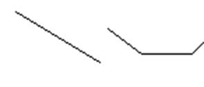
Figure 4-2. Example of Line Features
C. Polygon: A closed connection between three or more discrete locations represented by X and Y (and in some cases Z) coordinates on a reference coordinate system, as shown below in Figure 4-3. Polygons with interior portions excluded (i.e. doughnut holes) are acceptable, but multipart polygons (i.e. separate polygonal shapes represented by a common database record) are not.
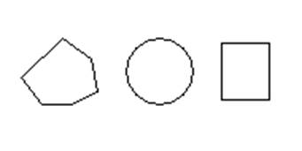
Figure 4-3. Example of Polygon Features
D. Complex Geometry Types: Arcs, circles, and ellipses are not included in this standard. This is intended to facilitate data exchange between software that processes these complex data types differently. However, these shapes may be represented by polylines or polygons as appropriate. For example, if arcs are used in a CAD drawing, they must first be broken into a line with vertices placed at intervals that are sufficient to maintain the accuracy requirements described in PEGS V1, Appendix 1E.1 Feature Types.
The placement of geometric features in juxtaposition to one another (i.e., next to, connected to, or on top of) is referred to as a topology. Topology rules establish requirements for the placement of features in relation to one another and in relation to features in other feature types. Unless stated otherwise, this standard requires the following topological rules:
A. Line Feature Types: Lines should contain one or more line segments with vertices placed at required intervals so the line feature does not stray from the actual feature by more than half the accuracy limit defined in PEGS V1, Appendix 1E.1 Feature Types for the feature type, as shown below in Figure 4-4.
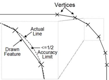
Figure 4-4. Placement of Vertices Along a Curve
Lines should begin and end at vertices collocated (i.e., exactly at the same coordinate) with features (often point feature types) designed to join two or more linear features, as shown in Figure 5. An example is electrical conduit lines that are joined only at junction boxes and other similar point features. For lines not naturally joined by physical features (e.g., marking lines), beginning and ending nodes should be placed where an attribute or other property change occurs.
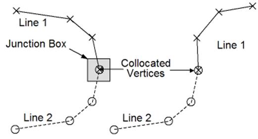
Figure 4-5. Collocation of Line End Points
B. Polygon Feature Types: Polygons must always be closed, meaning all vertices must be shared by two adjacent line segments forming the edges of the polygon, as shown in Figure 4-6.
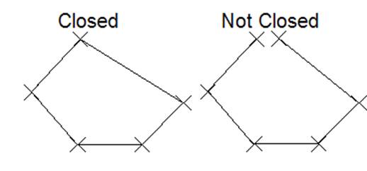
Figure 4-6. Examples of Closed and Unclosed Polygons
Unless otherwise stated, polygons must not overlap other polygons of the same feature type, as shown in Figure 4-7. This includes polygons placed on top of other polygons, as well as small overlapping splices because one or more vertices of adjacent sides are not matched. Polygons placed within (e.g., a ‘doughnut hole’) a larger polygon (e.g., the ‘doughnut’) which do not overlap are acceptable, because they describe a physically different space from the surrounding polygon.
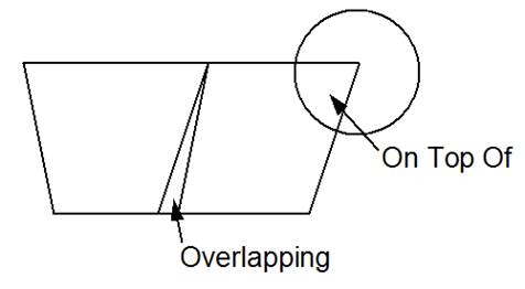
Figure 4-7. Overlapping Polygons
Polygons must share vertices with adjacent polygons where the real-world features they represent are adjacent, as shown below in Figure 4-8. This rule applies to polygons in the same feature type as well as polygons of different but related feature types.
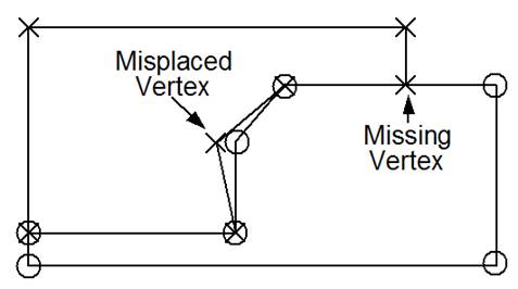
Figure 4-8. Placement of Vertices of Adjacent Polygons
4.2.3 Relationship of GIS & CAD Layers
Because many more CAD layers can be used to represent the same features represented on far fewer GIS layers, there is a natural many-to-one matching of CAD to GIS layers. The specific relationship of CAD layers that correspond to GIS layers is shown in PEGS V1, Appendix 1E.2 – Cross Reference of CAD and GIS.