6.2 Utilities
6.2.1 Underground Utility Markings
The design and construction of all projects at BWI Marshall and Martin State Airports shall include the requirement to mark all temporary (regardless of duration) and permanent underground utilities with detectable utility warning devices in accordance with the following requirements:
In paved areas (asphalt or concrete) mark the underground utility with 6” wide detectable tape positioned at a maximum 3"- 6" deep below the bottom of asphalt or concrete.
In unpaved areas mark the underground utility with 6” wide detectable tape positioned at a maximum 8"- 12" deep below top of ground.
6.2.1.1 Underground Utility Marking Requirements
A. Buried Underground Non-metallic Utilities:
1. All temporary and permanent buried underground non-metallic utilities shall be marked with appropriately colored detectable utility warning tape placed over the utility at the depth indicated above.
2. Additionally, all temporary and permanent buried underground non-metallic utilities shall also be marked with a steel reinforced copper clad tracer wire placed with and at the same depth as the utility. The tracer wire shall be continuous (thru) and shall be brought into and be accessible at all valves, handholes, manholes, and other access points along the length of the utility. Should the tracer wire be terminated at these locations, 5 or more feet of spare wire shall remain and be coiled.
B. Buried Underground Metallic Utilities:
1. All temporary and permanent buried underground metallic utilities shall be marked with appropriately colored detectable utility warning tape placed over the utility at the depth indicated above.
C. Underground Non-metallic Utilities installed by directional drilling or other trenchless technologies:
1. All temporary and permanent underground non-metallic utilities installed by trenchless technologies such as directional drilling, jack and bore, etc, shall include the placement of an appropriately colored steel reinforced copper clad tracer wire placed with and at the same depth as the utility. The tracer wire shall be continuous (thru) and shall be extended beyond the limits of the trenchless installation and be brought into and be accessible at all valves, handholes, manholes and other access points along the length of the utility. Should the tracer wire be terminated at these locations, 5 or more feet of spare wire shall remain and be coiled.
D. Underground Metallic Utilities installed by directional drilling or other trenchless technologies:
1. Metallic utilities installed by trenchless technology shall not be marked for the extent of the trenchless installation, but they shall be marked in accordance with the requirements of Paragraph 2, Buried Underground Metallic Utilities, for all portions of the utility installed by conventional trenching.
E. Utility Marking Materials shall conform to the following requirements:
1. Detectable Utility Warning Tape:
The detectable tape shall be 6” wide and 5.0 mil thick, continuously inscribed with a description of the utility (Gas, Water, Electric, etc.), color coded to meet the American Public Works Association (APWA) uniform color code system as listed below and shall include a metallic foil coating that is detectable by utility locating equipment.
|
RED |
Electric Power Lines, Cables, Conduit and Lighting Cables |
|
YELLOW |
Gas, Oil, Steam, Petroleum or Gaseous Materials |
|
ORANGE |
Communication, Alarm or Signal Lines, Cables or Conduit |
|
BLUE |
Potable Water |
|
GREEN |
Sewers and Drain Lines |
|
PURPLE |
Reclaimed Water, Irrigation and Slurry Lines |
|
PINK |
Temporary Survey Marking |
|
WHITE |
Proposed Excavation |
2. Steel Reinforced Copper Clad Tracer Wire: Tracer wire shall be a 12 AWG, Extra-High-Strength Copper-Clad Steel conductor (EHS-CCS), insulated with a 45 mil, high-density, high molecular weight polyethylene (HDPE) insulation, and rated for direct burial use at 30 volts. EHS-CCS conductor must be a 21% conductivity for locatability purposes. Break load shall be a minimum of 1,150 pounds. HDPE insulation shall be Restriction of Hazardous Substances (RoHS) compliant and utilize virgin grade material. Insulation color shall meet the APWA uniform color code system, as listed above, for identification of buried utilities.
Tracer wire shall be installed in the same trench and inside bored holes and casing with pipe during pipe installation. It shall be secured to the pipe as required to ensure that the wire remains adjacent to the pipe. The tracer wire shall be securely bonded together at all wire joints with an approved watertight connector to provide electrical continuity, and it shall be accessible at all trace wire access points. The contract shall require the tracer wire to be tested for continuity prior to acceptance of the utility.
F. Recommended product Manufacturers
1. Acceptable tracer wire products for buried installations include the following products or an approved equal:
a. Copperhead conventional tracer wire produced by Copperhead Industries, LLC (www.copperheadwire.com), or DURAtraceTM Produced by Duratrace (www.duratracewire.com)
b. Acceptable tracer wire products for trenchless technology installations include the following products or an approved equal:
c. SoloShotTM EHS produced by Copperhead Industries, LLC (www.copperheadwire.com), or DURAtraceTM DD Produced by Duratrace (www.duratracewire.com).
2. Acceptable detectable utility warning tape products for underground utility markings installations include the following products or an approved equal:
a. 6” wide and 5.0 mil thick, continuously inscribed with a description of the utility (Gas, Water, Electric, etc.), color coded to meet the American Public Works Association (APWA) uniform color code system and shall include a metallic foil coating that is detectable by utility locating equipment produced by Stranco, Inc. (www.strancoinc.com) or Rhino Marking and Protection Systems (www.rhinomarkers.com).
G. Recording of Marking Technique Used: CAD and GIS data that records the location of utilities should provide an indication where one of the marking techniques described above was installed and, if so, which type and manufacturer’s product was used.
1. As-built or record CAD should include a superscript number on any annotations used to label utility features in the drawing where a marking technique was used (i.e. 6” PVC Drainage Line). A schedule of corresponding notes on the same or a separate sheet, should list all such notes indicating the method of marking used, the manufacturer name, and product name or model number.
2. As a requirement of the As-Built submittal, GIS data submitted with subsurface utilities should record the use of, manufacturer name, and product or model in the description attribute (e.g. “Marked with Copperhead Industries’ SoloShotTM EHS tracer wire).
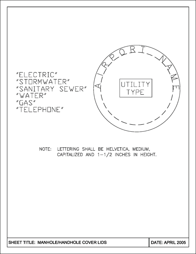
6.2.2 Manhole/Handhole Covers/LIDS
All new and replacement manhole/handhole covers/lids shall include customized cover/lid surface lettering as follows:
All Airport manhole/handhole covers/lids shall include the name “BALTIMORE/WASHINGTON INTERNATIONAL AIRPORT” or “MARTIN STATE AIRPORT” and the type of utility: “ELECTRIC”, “STORMWATER”, “SANITARY SEWER”, “WATER”, “GAS”, “TELEPHONE.” Lettering shall be Helvetica, medium, capitalized, and 1 ½ inches in height.
6.2.3 Water Mains
6.2.3.1 Backflow Prevention
Refer to Chapter 10 Plumbing for Backflow Prevention requirements.
6.2.3.2 Corrosion Protection for Water Valve Repair (New and Replacement Valves)
Valves and bolt assemblies for all new and replacement water valves shall be required to be protected from corrosion in accordance with the following specification and details.
A. Water Valve Notes and Specifications for New and Replacement Valves
New valves shall be non-rising stem, high pressure, resilient-seated gate valves sized to match existing, AWWA C509, ductile-iron body and bonnet with bronze or ductile iron gate, resilient seats, bronze stem and stem nut, 250-PSIG minimum working pressure, 400 PSIF test pressure, interior coating according to AWWA C550, and mechanical joint ends. All valves shall be standardized to close when turned in the clockwise direction “Right Handed”. The basis of design is Mueller Valve Model A2360 Series Resilient Wedge Gate Valve or approved equal.
1. Valves shall be gates valves conforming to the American Waterworks Association.
2. Epoxy coated inside and out.
3. Fasteners exposed to backfill must be T304 stainless steel.
4. O-ring seals.
5. Solid sleeves shall be ductile iron 250-PSIG minimum working pressure design.
Coat mechanical coupling and valve bolts in accordance with specifications and details below.
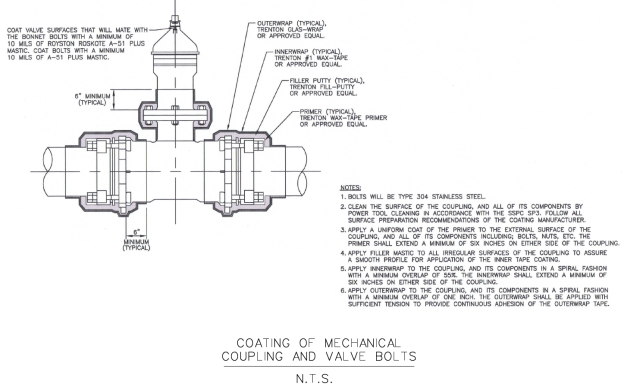
B. Specifications for Coating of Bolts and Mechanical Joints-Gate Valve Assemblies for New and Replacement Valves
1. External Coating System for Mechanical Couplings
a. Mechanical joints/flanges shall receive an exterior tape wrapping in the field as indicated in detail below. The coating applicator shall abide by and follow all manufacturer’s application specifications for the coating system. All components of the coating system shall be manufactured by a single supplier to assure compatibility of individual components. The coating system shall be manufactured by Trento Corporation or an approved equal.
b. Materials
I. Primer: A blend of microcrystalline wax, plasticizer, and corrosion inhibitors having a paste-like consistency, designed to displace moisture, penetrate rust and wet the surface, ensuring adhesion of the tape. The primer shall be Trenton Wax-Tape Primer or approved equal.
II. Filler Putty: A cold applied anti-corrosive moldable filler material used to even the contours of irregular fittings and surfaces. The filler putty shall have the following properties:
a. Specific gravity: 1.15
b. Density: 24 cu in/lb
c. The filler putty shall be Trenton Fill-Putty or approved equal. Filler putty shall be used at all irregular surfaces to provide a smooth surface for the application of the innerwrap and outerwrap.
III. Innerwrap: A non-woven, non-stitch bonded synthetic fabrix saturated with a blend of microcrystalline wax, plasticizer, and corrosion inhibitor (no clay fillers). The inner tape shall have the following properties:
a. Thickness: 70 to 90 mils
b. Dielectric strength: 170 volt/mil
c. The innerwrap shall be Trenton #1 Wax-Tape or approved equal.
IV. Outerwrap: A white, resin-coated, woven figerglass fabric. The outerwrap shall be the following properties:
a. Thickness: 0.005 inch
b. Tensile strength (per one inch width): 85 lb min
c. Tape width: 6 inches
d. The outerwrap shall be Trenton Glas-Wrap or approved equal
C. Application of Coating Materials
1. The mechanical couplings either side of the vale, including all components shall be fully coated for a minimum of 6 inches on either side of the coupling.
a. Clean the surface of the coupling, and all of its components by power tool cleaning in accordance with SSPC-SP3. Follow all surface preparation recommendations of the coating manufacturer.
b. Apply a uniform coat of the primer to the external surface of the coupling, and all of its components including; bolts, nuts, etc. The primer shall extend a minimum of six inches on either side of the coupling.
c. Apply filler mastic to all irregular surfaces of the coupling, with special attention to the bolts, to assure a smooth profile for application of the inner tape coating.
d. Apply innerwrap to the coupling, and its components in a spiral fashion with a minimum overlap of 55%. The innerwrap shall extend a minimum of six inches on either side of the coupling.
e. Apply outerwrap to the coupling and its components in a spiral fashion with a minimum overlap of one inch. The outerwrap shall be applied with sufficient tension to provide continuous adhesion of the outerwrap tape.
6.2.4 Sanitary Sewers
If existing conditions prohibit gravity flow then lift station/ejector pits are to be included in the design. Lift stations and ejector pits should be located outside the footprint of the building structure the restroom is within. In addition, secondary containment of the lift station and ejector pit should be considered to limit overflow into adjacent areas during system failure.
If a lift station or ejector pit is required, this MUST be brought to the attention of the MDOT MAA Office of Engineering & Construction during the design process. The exact requirements of the design will then be provided for inclusion in the project construction documents.
SEWAGE EJECTOR PIT DESIGN: All projects with sewage ejector pits should be designed with the ejector motors, pumps, impellers and related equipment outside the actual “sewage pit.” One acceptable method is to construct a wetside/dryside pit. All motors, pumps, impellers, and equipment would be installed on the dryside with pipe connections to the wetside (sewage pit side). The dryside of the pit would be sealed tight to prevent water and sewer gases infiltration. Other concepts will require the approval of the MDOT MAA Office of Engineering & Construction project manager and the Office of Facilities Maintenance. Refer to Chapter 7.6 Restroom Standards for further information on sewage ejection pit design.
6.2.5 Electric/Phone/Telecommunications
Parking facilities shall be equipped with public telephones. The Contractor should install the concrete pad and necessary conduits at the phone location. The telephone company (currently Verizon) should pull wiring and install housing and telephone.
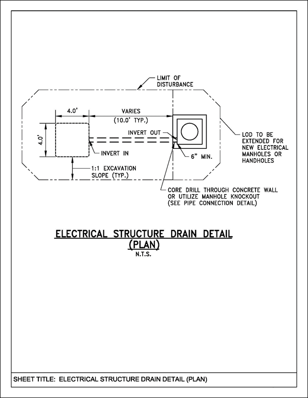
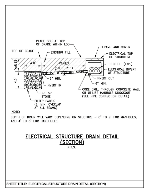
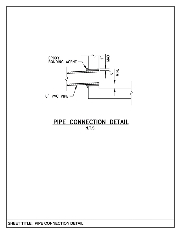
6.2.5.1 Electrical Structure Drains
An Electrical Structure Drain (ESD) shall be provided as a drainage design alternative for electrical manhole (MH) and handhole (HH) structures where other preferred alternate drainage measures may not be possible to facilitate drainage away from the Electrical and Communications (E/C) Infrastructure Systems.
Qualifying Preferred Alternate Drainage Measures are the following:
A. Install 6” Polyvinylchloride (PVC) drainage pipe from E/C MH or HH directly into a drainage MH in close proximity provided inverts permit positive drainage.
B. Install 6” PVC drainage pipe from E/C MH or HH directly into drainage pipe in close proximity provided inverts permit positive drainage.
ESD(s) shall be installed in locations where space is available and where other preferred drainage measures cannot be provided in grass areas. For proposed E/C ductbank installations the design consultant shall provide either adequate space for ESD installations at an E/C structure or design the ductbank plan and profile to allow for the E/C ductbank infrastructure to drain to a low point at a MH or HH where an ESD can be installed.
Many design measures have been taken in the past to prevent water from entering the E/C infrastructure at lighting conduits, manholes, handholes, etc., however water has entered the E/C infrastructure despite those efforts, and design measures need to be taken to remove the water that has both entered in the past and will continue to enter in the future. For existing E/C ductbank runs, ESD(s) need to be installed at ductbank profile low points at E/C MH(s) and HH(s) where space is provided.
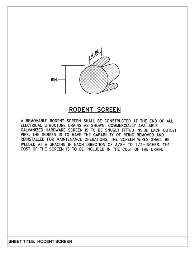
The following details depict the plan and section view of a typical ESD, section view of a typical pipe connection detail, and the plan view of a typical rodent screen detail.
6.2.6 Use of HDPE Pipe
A. HDPE Pipe is acceptable for underground use at BWI Marshall and MTN Airports for Sanitary Force Main, Natural Gas Distribution, communications conduit, and for electrical system directional bore. HDPE Pipe is prohibited for use with potable water and Fire Protection Water Systems or with glycol recovery drain/force main piping. HDPE Pipe is also prohibited for use inside railroad right-of-way.
B. Material Requirements:
1. High Density Polyethylene (HDPE) Pipe and Heat Fusion Fittings shall conform to AWWA C906, PE 3408. Pipe and fittings shall have a minimum standard dimension ratio (SDR) of eleven (11) rated for 160 psi and have a nominal ductile iron pipe size. Butt Fusion Fittings shall meet the requirements of ASTM D-2153 and ASTM D-3261.
2. Use Butt Fusion Joining Technique for joining pipe segments and pipe fittings in accordance with the pipe manufacturer’s written specifications. Mechanical couplings are not permitted for joining segments of HDPE pipe underground. Flange or other pipe adapters for connection to valves or dissimilar pipe materials inside vaults or underground shall be as recommended by HDPE Pipe Manufacturer.
3. Contractor shall certify that all joining operations are conducted by personnel trained by the joining equipment manufacturer. Certification shall be provided to the Resident Engineer prior to construction.
C. High Density Polyethylene Pipe (SDR 11) is furnished with inside diameters less than nominal pipe size which needs to be considered when determining pipe flow and velocity capabilities.
D. All underground natural gas and sanitary force main installations must be buried with at least 36-inches of cover from top of pipe to finished grade. Pipe bedding shall consist of a minimum of 4” depth of compacted sand, peagravel, or small diameter clean aggregate placed all around HDPE Pipe with select backfill above to bottom of pavement subgrade. Tape continuous length of No.12 AWG Copper insulated tracer wire to top of pipe and install 6-inch wide by 5 mils thick detectable warning and identification tape centered directly above pipe.
E. Testing:
1. Sanitary Force Main: Conduct piping tests before joints are covered. Fill pipeline 24 hours before testing and apply test pressure to stabilize system. Perform Hydraulic Test with pressure at 150 PSI for two hours. There should be no leakage. Remake leaking joints with new materials and repeat test until leakage is stopped.
2. Natural Gas Distribution: Conduct air pressure test per NFPA 54 on the gas system piping for at least 24 hours. Test pressure shall be 100 PSI. During the test, the entire system shall be completely isolated from all compressors and other sources of air pressure. Locate and repair leaks found and retest line until pressure holds for 24 hour test period.