7.4 Floor and Wall Coverings
7.4.1 Restrooms
Refer to Restroom Standards in Chapter 7.6 Restroom Standards for Restroom floor and wall coverings.
7.4.2 Tile
A. Red Ceramic Tile Column Finish: Summitville Tile, Inc., Summitville, Ohio 43962, manufacturers the red tile which clads the columns in front of the Passenger Terminal. The custom color number is 4865-1.
B. No asbestos containing materials are to be used, including mastic.
7.4.3 Carpet Tile
A. Terminal E Carpet Tile: Carpet tile used in Concourse E Holdrooms is manufactured by Shaw Industries, Inc. The product is Networx Hemisphere No. SC-32, color 4295B-11. The field is 3 ply Dupont Antron Lumina, 2 end No. C145A and 1 end No. C151A. The border is 2 ply Dupont Antron Lumina, 1 end No. C127A and 1 end No. C247A.
B. Domestic Terminal Carpet Tile: The Consultant shall coordinate selection of carpet with the MDOT MAA Resident Architect.
7.4.4 Painting
Architects shall specify “white” paint colors that are standard with the MDOT MAA Office of Facilities Maintenance in order to minimize the paint colors they have to keep on hand.
7.4.5 Wall Covering
The wall covering used in the public areas of the Domestic Terminal shall be the MDOT MAA standard.
7.4.6 Solid Surfacing Material
A. Domestic Terminal’s Public Area: The solid surfacing material for the Domestic Terminal’s public area wainscot shall be coordinated with the MDOT MAA Resident Engineer.
B. Terminal E Casework: The solid surfacing material for Terminal E casework is Wilsonart Steel Grey Tempest – 9194TM at 13 mm thickness.
7.4.7 Plastic Laminate
Terminal E Casework: The Plastic Laminate used for Terminal E casework shall be Nevamar “Phantom Grey Matrix Crystal” MR-6-7CR, and “Storm Grey Matrix Crystal” MR-6-4CR.
A. Waterproofing of suspended composite and reinforced concrete floors in janitors’ closets, toilet rooms, kitchens, food preparation areas and any other spaces where the use of the space, potentially or consequently, results in the wetting of the floor. These spaces are referred to as “wet areas” in this Standard.
B. Prevention of water damage from hot water heaters and sprinkler drains.
SPECIAL NOTE:
Consultants shall not place wet pipes over electrical rooms (such as electrical substations, communications rooms and other spaces where water damage would have significant impact on life safety or the airport’s operations or that of its tenants). For special conditions that prohibit this, it should be brought to the attention of the Building Permit Committee or the MDOT MAA Project Manager. This may result in additional provisions being required beyond those contained in this Standard.
7.4.8.1 Waterproofing of Floors
A. Waterproofing of floors in wet areas is intended to prevent water damage to spaces below or adjacent to the wet area.
B. Waterproofing of floors in wet areas shall be continuous. The waterproofing may be a membrane material or a liquid-applied material and must have acceptable waterproofing and crack-suppression qualities. The material must be laid in full compliance with the manufacturer’s instructions.
C. Acceptable membrane materials are “Schluter-Ditra” membrane and underlayment as manufactured by Schluter Systems, or equal materials approved by MDOT MAA.
D. Acceptable liquid-applied materials are “Redgard” waterproofing and crack prevention membrane, as manufactured by Custom Building Products, or equal materials as approved by MDOT MAA.
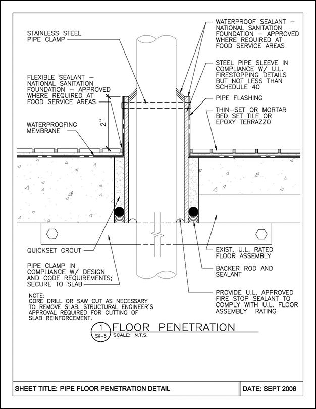
E. At perimeter walls of wet areas and at pipe and other projections above the floor slab, turn up floor waterproofing minimum 2” onto the vertical surface, so that the wet area is surrounded by a continuous waterproof barrier to prevent water penetration into surrounding spaces. Refer to Standard detail for Floor Penetration on the following pages.
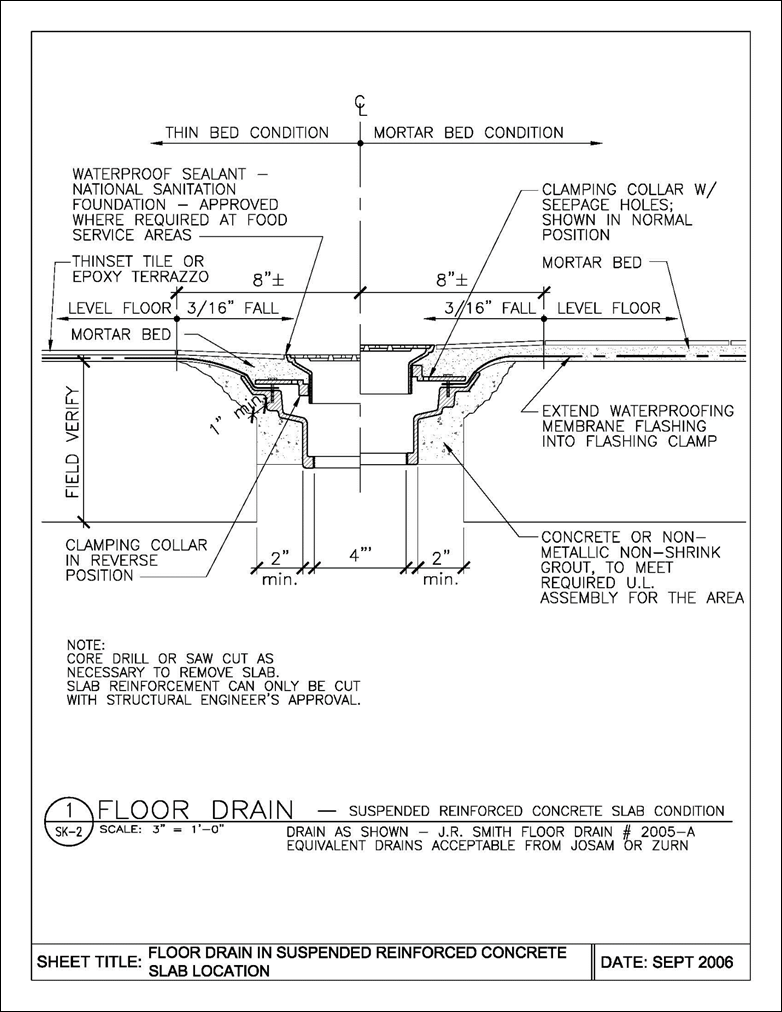
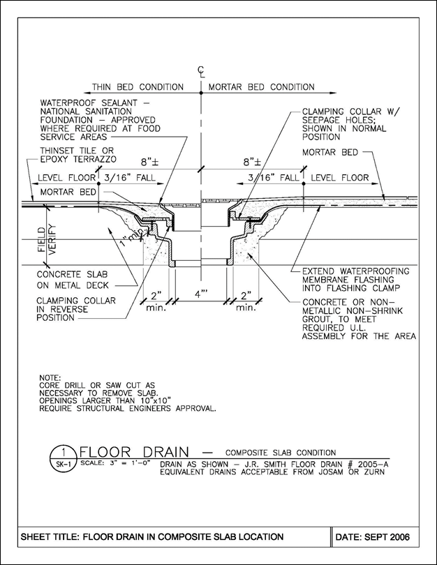
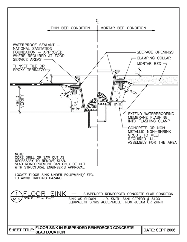
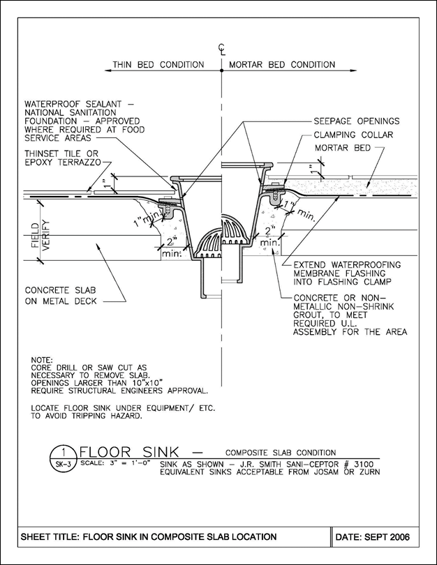
7.4.8.2 Floor Drains, Floor Sinks and Floor Cleanouts
A. Refer to the standard details for floor drains and floor sinks on the following pages.
B. Floor drains, floor sinks, and floor cleanouts in food preparation spaces must comply with the requirements of Anne Arundel County Health Department.
C. Floor sinks, floor drains, and floor cleanouts in wet areas generally must comply with the following requirements:
1. Floor sinks, drains, and cleanouts must be provided with flanges to allow the floor waterproofing to be flashed around the flange and secured with continuous flashing clamps. Where necessary to allow for smooth transition of floor waterproofing onto flange, cut back the topping of the slab as illustrated.
2. Floor sinks and drain must have seepage openings to allow moisture penetrating the floor covering to discharge into the body of the sink/drain. Provide loose gravel at seepage openings.
D. Size of floor drains and sinks.
1. Grids of drains and sinks shall be not less than 8 inches in diameter, or 8” X 8” square. Rectangular grids shall not be less than 50 square inches in area.
2. Floor drains and sinks must have outlets not less than 4 inches diameter to discharge into drain piping not less than 4 inches in diameter.
E. Cleanouts
1. Cleanouts below the slab shall only be located above service areas or other unoccupied spaces, where access to them will not inconvenience other Tenants or the Public.
2. Where cleanouts below slab level are not permissible, provide side-accessible cleanouts in walls above the slab, such as walls of mechanical chases or other walls in Tenant’s premises.
3. Cleanouts shall not be permitted in electrical substations, communications rooms and other similar spaces.
7.4.8.3 Penetrations Through Floors of Wet Areas
A. Refer to the standard details on the following pages.
B. Penetrations through slabs for new sinks, drains and pipes must not impair the structural stability of the slabs. Existing suspended slabs at the Airport are generally of the following types (Consultant must verify this information in the field):
1. Composite concrete, generally 4-1/2 inches thick, with 2-1/2 inch concrete topping on 2 inch metal deck.
2. Reinforced concrete. Thickness varies, from approximately 6 inches to 8 inches.
C. General Requirements for Floor Penetrations
1. Submit drawings and documents signed and sealed by a structural engineer registered in the State of Maryland.
2. Locate penetrations through slabs so that they are clear of below-slab beams.
3. For reinforced concrete slabs, locate penetrations so as to avoid the slab reinforcement. Slab reinforcement is likely to be heavy in the areas surrounding columns. Where penetrations through reinforced concrete slabs are so located or of such a size that cutting of slab reinforcement bars is unavoidable, provide specific details signed and sealed by a structural engineer.
4. For composite slabs, for any penetrations larger than 10” X 10” through the slab, provide specific details signed and sealed by a structural engineer.
7.4.8.4 Floor Coverings
A. Impervious tile or epoxy terrazzo is required in wet areas. Portland-cement based terrazzo is not permitted. An epoxy-type grout is recommended for tiled floors. At junction of floor finish and floor sinks/drains/cleanouts, provide flexible sealant. (National Sanitation Foundation approved where required at food service areas.)
B. At perimeter walls, etc., turn floor covering up as a wall base and to protect turned-up vertical waterproofing.
7.4.8.5 Preventative measures to avoid water damage to floors from water heaters, sprinkler drains, etc.
A. Install hot water heaters (high level) over a curbed galvanized metal or other catchment tray, with a discharge pipe to discharge at a floor sink, mop sink or floor drain with a funnel.
B. Install hot water heaters (floor mounted) on a curbed waterproof tray raised sufficiently above the floor so that the tray discharge pipe can fall to discharge at a floor sink or floor drain.
C. Sprinkler drains must discharge over an adequately sized floor drain or floor sink.
7.4.8.6 Test for Waterproofing of Floors
A. Test of all wet areas as defined and required to be waterproofed should be tested to ensure that the requirements and recommendations in the standards have been successfully applied and that all spaces below and adjacent to the wet areas are protected from water penetration and moisture damage.
B. Items to be Tested:
1. Waterproofing of Floors:
a. Continuity of membrane and/or liquid-applied material.
b. Perimeter walls to a min.1-1/2 inches height above the contributory area.
c. Projections of pipe and other material above the floor.
2. Floor Drains, Floor Sinks and Floor Cleanouts:
a. Prevention of migration of water to occupied spaces below any wet area to be waterproofed in conformance with Chapter 7.4.8 Waterproofing water proofing standards.
C. Cost of the flood test shall be borne by the tenant, not the Airport.
D. The flood test shall include testing of:
1. Each wet area to be waterproofed in conformance with Chapter 7.4.8 Waterproofing standards.
2. All floor drains, floor sink drains, and clean outs in and serving each wet area.
3. Ensure that all corners and door threshold are thoroughly tested.
E. Test Procedure: The flood test shall be performed in conformance with the following:
1. Ensure that all new sanitary pipe drains are pre-tested for leaks and proper drainage prior to the wet area flood test.
2. Allow for manufacturer’s recommended dry and cure time for the installed water proof membrane before conducting testing.
3. Notify the MDOT MAA Office of Commercial Management ten calendar days prior to testing to obtain access and an access schedule for the spaces being tested and the spaces located below and adjacent to the areas to be tested.
4. Prior to testing, remove acoustic ceiling panels in spaces located beneath test area.
5. Prior to testing, provide access into the ceiling/under slab space, in any areas with drywall ceiling that are located beneath the test area.
6. Prior to testing, provide protective plastic sheet covering to all equipment, and furniture in any occupied areas located immediately below or adjacent to the wet floor being tested.
7. Prior to testing, provide protection of doors into and out of the space being tested.
8. Provide a seal at the sill (threshold) of each door into and out of the space being tested.
9. Provide observers in the areas located immediately below the wet area being tested.
10. Equip the testing team with devices that will permit communication between the wet floor area being tested and the areas immediately below and adjacent to the wet area being tested.
11. Provide each of the observers with a reporting form that when filled out will locate any leaks for use during subsequent resealing operations.
12. Install plugs in the floor drains in the wet floor being tested.
13. Flood each area to a depth of 1-1/2 inches above the highest finish level of the contributory area. (That is to ½ inch below the two-inch height of the turned up membrane located at the edges of the contributory area).
14. Maintain 1-1/2 inches of water in the wet area for a minimum of 2 hours.
15. Observe and report any leaks using the forms and communication devices called for above.
16. Identify source of leak on top side of slab.
17. After two hours of testing, unplug floor drains and allow water to drain out of the wet area.
18. After one hour, observe again, the conditions in areas below and adjacent to the test area.
19. Upon completion of the test replace all removed acoustic ceiling panels and repair any drywall ceiling modified to provide testing access. Remove all protective plastic sheathing and return the space to its original condition.
F. Report: Compile a report summarizing the test and specifically locating and describing any leaks that occur. Include the observers filled out forms as well as a diagram showing where the sources of the leaks are located. Provide two copies of the report to:
MDOT MAA Inspector and/or the Resident Engineer,
991 Corporate Boulevard
Linthicum, Maryland 21090
G. Re-test: After sealing leaks, re-test the wet area as specified above. Continue sealing leaks and testing until all leaking has been eliminated.
H. Repair: The contractor will be responsible for all damage, caused by the test, in areas which are located adjacent to and below the test area.
7.4.9 Floor Structure Recessed Expansion Joint Covers
The consultant of new or renovated facilities shall specify floor structure expansion joints with recessed/flush metal covers when and wherever possible. The intent of the required covers is to reduce potential tripping hazards and, secondarily, to protect the expansion joints. This standard addresses both floor to floor and floor to wall expansion joints.
The need for, location of, performance requirements and type of expansion joints will be determined by the consultant as required by the type of floor construction, floor finishes and current design code requirements.
A. General Requirements – All expansion joint covers shall be:
1. Recessed and flush with adjacent finishes or slab surface.
2. ADA Accessibility Guidelines-compliant.
3. Heavy duty, as appropriate, for the anticipated traffic over the joint.
4. UL fire-rating, as appropriate, where installed in a fire-rated assembly.
5. Weatherproof when exposed to the weather with occupied spaces below (including parking garages). Covers subject to snowplowing should be designed to withstand this activity.
6. Stainless steel or aluminum, as appropriate, with finishes to be determined by Consultant. Ensure proper isolation barriers are specified for aluminum on concrete installations.
7. The Consultant shall consider the coefficient of friction of adjacent floor/slab surfaces when selecting the cover plate and its finish. Plate texturing or applied non-skid treatment may be applicable with certain adjacent finishes.
8. Joint covers over bellow type expansion joints should be removable to allow cleaning.
9. The cover should span all components of the expansion joint.
B. New Construction Guidelines – For new construction in the Terminal, and other buildings with applied floor finishes, the expansion joint covers shall accommodate and be appropriate for the floor finishes on each side of the joint. These finishes typically include: carpet, vinyl composition tile, ceramic tile and terrazzo. Where the recessed expansion joint cover also acts as a transition between two types of floor finishes, the consultant shall specify a cover that is designed for such transitions.
C. Existing Construction Guidelines – Consultants of building renovations that include existing floor structure expansion joints within the limits of work must provide the MDOT MAA with an evaluation of the structural feasibility and probable costs to modify or replace existing expansion joints to allow for a recessed flush cover plate installation. Based on the evaluation, the MDOT MAA will decide on whether to modify the existing joints to comply with the requirements of this standard.
NOTE: Floor structures in the Hourly, Daily and Consolidated Rental Car Facility Garages are post-tensioned concrete slabs. The Consultant should take particular care in attempting to modify existing expansion joint configurations in this type of structure.
D. Interior Floor Expansion Joint Covers and Assemblies
1. General: Floor expansion joint covers required to bridge building structure expansion joints must be of a type recommended by manufacturers for installation in airports, and capable of withstanding the loads imposed by airport pedestrian traffic; wheeled carts of various capacities and wheel types; pallet trucks; trolleys; and commercial ride-on floor cleaning equipment. Covers must be all-metal design, flush with adjacent floor finishes such as tile and terrazzo to avoid tripping hazards, and textured or striated for slip resistance. Set expansion joint covers adjacent to carpeted floors slightly below the finished height of carpet to compensate for carpet crushing and wear.
2. Expansion joint assemblies consist of an approved expansion joint cover and fire barrier.
E. Expansion Joint Covers
1. Solid cast or extruded aluminum, or combination, no-bump type expansion joint covers are required. Minimum product design characteristics and performance requirements include the following:
a. Material: Heavy-duty interlocking aluminum extrusions.
b. Movement: Three-way.
c. Load Capacity: Minimum 1450 psi for solid rubber tires.
d. Capable of spanning width of expansion joint.
e. Designed to reduce noise, and resist passage of liquid spills and accumulation of dirt in movement joints.
f. Americans with Disabilities Act Accessibility Guidelines (ADAAG) compliant.
2. Installation Accessories: Factory-fabricated closure materials, intersections, and similar accessories required for a continuous expansion joint system. Isolate aluminum components from concrete and dissimilar metals following expansion joint cover manufacturers’ recommendations and details.
3. Expansion joint covers incorporating elastomeric materials in the design of the wearing surface, including santoprene, have not been capable of withstanding the conditions at the airport. Aluminum extrusions of this type of cover are generally thin-walled and susceptible to damage. Additionally, elastomeric extrusions tear easily and are often of a unique design. Obtaining matching replacements of the correct design has proven to be difficult for airport maintenance. Expansion joint covers of this type are not permitted.
F. Fire-Resistance-Rated Expansion Joint Assemblies
1. General: Floor fire-resistance-rated expansion joint assemblies must be of a type that is an approved fire-resistant joint system, designed to resist the passage of fire for a time period not less than the required fire resistance rating of the airport terminal floor, or other horizontal fire separation assembly. Where expansion joint covers are a part of fire-resistance-rated horizontal construction, expansion joint covers do not contribute to the overall fire-resistance rating of the floor assembly. Details must provide for the installation of the expansion joint covers, and not less than the minimum thicknesses of floor materials required to install the fire-resistant joint material in compliance with assemblies tested by laboratories recognized by the MDOT MAA Office of the Fire Marshal. For example, if the tested assembly requires a minimum four-inch depth of concrete either side of the fire-resistant joint material, the overall concrete depth at the expansion joint must be increased by the depth required for flush installation of the joint cover. Generally, the overall required thickness of concrete at the expansion joint will be greater than the thickness required for a fire-resistance-rated composite slab.
2. Fire Barrier Joint Material: Manufactured product consisting of a combination of traffic-bearing silicone top layer applied to a fire-retardant-impregnated foam core and intumescent bottom layer. Joint material is adhered to the edges of concrete floor slabs. Factory pre-formed transitions to reduce or eliminate field cutting are required wherever possible. Completed installation must be designed to produce a fire-resistance-rated watertight joint.
Bellows type fire barriers are not permitted, unless otherwise accepted by MDOT MAA. These types of joints have become travel paths for various pests and should be avoided.
3. Fire-Resistant Joint Design: Joint designs cannot include permanent metal concrete pour stops without greatly reducing the required fire-resistance rating of the horizontal assembly. Metal acts as a thermal bridge, resulting in premature failure of the joint when tested. Expansion joint details should indicate removal of the pour stops, or alternative methods of controlling concrete pours during construction.
Note that many existing structural expansion joints utilized metal pour stops that were left in place. In order to comply with fire-resistance-rated horizontal separation requirements, these pour stops may have to be removed. Additionally, concrete slab thicknesses may not comply with tested assembly details. In existing construction, extraordinary measures may be required to sawcut pour stops and thicken slab at expansion joints.
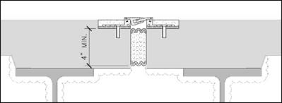
Figure 1 Representative expansion joint cover and fire barrier.
4. Non-Conforming Joint Designs: Although not recommended or encouraged, Consultants, in consultation with MDOT MAA Office of the Fire Marshal and the expansion joint manufacturer’s technical support, may seek to obtain an engineering judgment, prepared by a registered fire protection engineer (FPE), for joint designs not in full compliance with laboratory-tested assemblies. The FPE need not be registered in the State of Maryland but must be certifying design on behalf of the expansion joint manufacturer.